Figures & data
Table 1. Compilation of different nuclear processes to release neutrons from atomic nuclei with examples for the corresponding neutron yield and facilities using the respective processes. The table is based on reference [Citation3].
Figure 1. Schematic drawing of a possible target-moderator-reflector-shielding assembly of a Low Energy accelerator-driven Neutron Source LENS. The proton beam power on the target can be on the order of 100 kW (see SONATE and HBS projects) with target dimensions of approximately 10x10x1 cm2. The target is entirely surrounded by the thermal moderator covering close to 4π in solid angle. The moderator in turn is encased by the reflector. Such an arrangement minimizes the loss of neutrons released within the target. In the extraction channels for thermal neutrons, one-dimensional cold finger moderators can be inserted, which are optimized for the specific application and become integral part of the instrument.
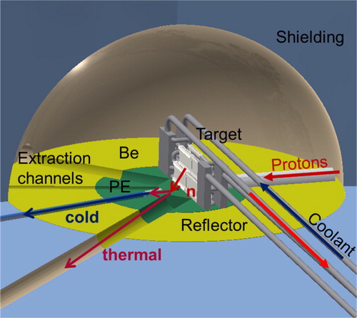
Figure 2. Schematic drawing of the three experimental areas surrounding the three target stations of the HBS in its reference design. Protons from the LINAC (only the last section shown to the left) are guided towards an upper level, distributed by a beam multiplexer and fed from above into three target stations operating at 24, 96 and 384 Hz. The target stations are surrounded by concrete walls as biological shielding. Instruments fitting to the respective pulse structure are grouped around the individual target stations. The reference design includes one instrument of each common type, but more instruments can be added or the instrument suite adapted to the needs of the respective user community. As an example, a dedicated target station for industrial research could be added.
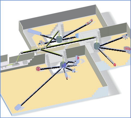
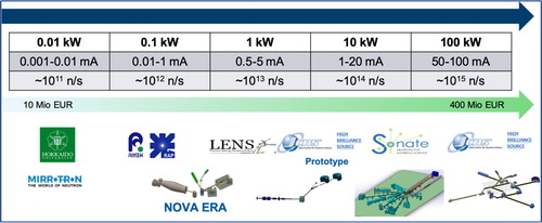
Figure 3. Schematic illustration of the scalability of CANS LENS in terms of proton beam power, proton beam current, source strength and required investment budget. At the bottom of the figure, examples of corresponding facilities or projects are depicted.