
Figures & data
Figure 1. HBS baseline design with the Linac to the left, a beam multiplexer in the center serving three individual target stations at three experimental areas.
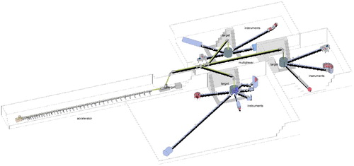
Figure 2. Neutron yield for various target materials [Citation5].
![Figure 2. Neutron yield for various target materials [Citation5].](/cms/asset/e8a1311c-d5d6-4252-bcea-54898e75b284/gnnw_a_1819132_f0002_c.jpg)
Table 1. Accelerator parameters used in the HBS Project.
Figure 3. HBS tantalum target with fin-like μ-channel structure.
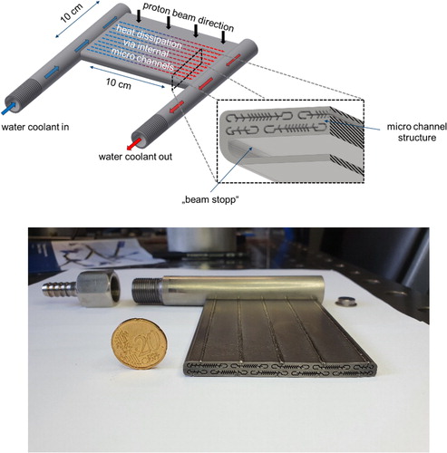
Figure 4. HBS target/moderator/shielding assembly.
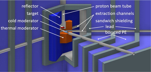
Figure 5. Prototype design and realization of the cold finger moderator with o/p H2 mixing cryostat.
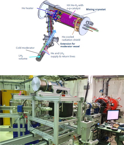
Figure 6. Possible positioning of up to six extraction channels within the thermal moderator close to the target. Here an arrangement with the proton beam hitting the target from aside is shown.
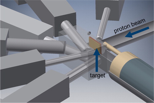
Table 2. Analytically calculated instrument parameters for HBS