Figures & data
Figure 1. Schematic plan of Laval Immigration Holding Centre (IHC), designed by Chernoff Thompson Architects, published on a Canadian government tendering website. Plan adapted from Schematic Design Report, 2017. Government of Canada, Public Works and Government Services, “1.3 Drawings,” ARCHIVED Immigration Holding Centre A&E Project (EF944-171885/B). (© Chernoff Thompson Architects.)
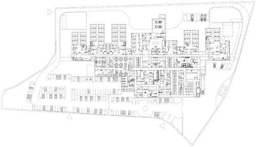
Figure 2. A 3D rendering of the Laval IHC, as designed by Lemay Architectes. The massing of the building has been rearranged significantly in comparison to the first schematic plan. The front bar, assumed to be administrative, forms both a physical and visual barrier between the public and the accommodation areas of the center, preventing the public from entering or viewing inside the facility. While privacy is a concern, the form of the building also aids in actively obscuring the process of detention occurring behind its façade. (Rendering from CBSA, Access to Information Request A-2019-00781.)
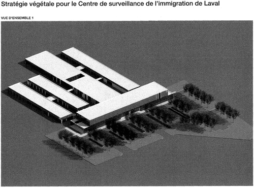
Figure 3. The site of the Laval IHC is in Laval, a suburban city separated from Montreal by the Prairies River. The geographic siting of the project, away from the city center, along an industrial road, further others the spaces of detention through its distancing from the general population. (Map by author.)
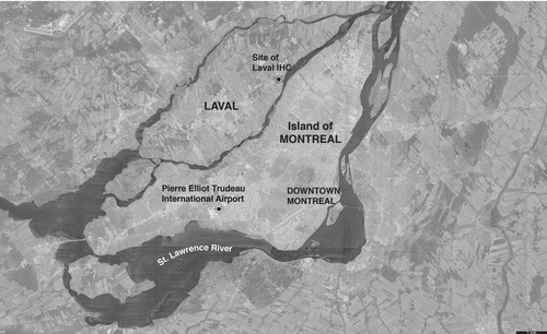
Figure 4. Site of the Laval IHC located adjacently to a road that connects several provincial and federal correctional facilities. Site 1 is the site of the existing Laval IHC in operation. Site 2 is the Leclerc Provincial Prison for women. Sites 3 and 4 are the Federal Training Centre, a maximum and minimum security prison.
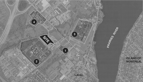
Figure 5. Vegetation strategy for the Laval IHC. A rendering and section illustrate how newly bought trees will be planted closest to the detention center and how mature trees will be preserved when farthest from the “physical and visual security zone,” which includes the outdoor detainee areas. While vegetation works to mask the facility from the public, vegetation is not to be enjoyed by detainees. (Drawing and rendering from CBSA, Access to Information Request A-2019-00781.)
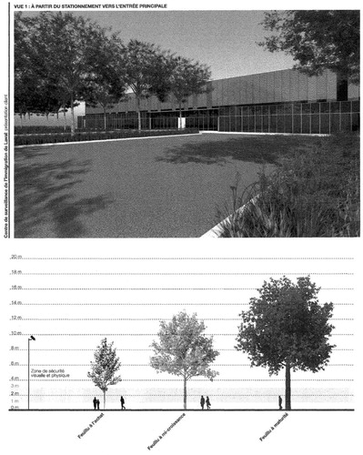
Figure 6. Typical dimensions of “devices” in relation to the human body, as adapted from Ernst Neufert’s Architects’ Data (1936), a standard reference guide for human measurements. The cultural connotations embedded within these devices relate to prison design, as most are employed in the construction of penitentiaries; however, in this context, they have been repurposed for the surveillance and control of migrants. (Drawing by author.)
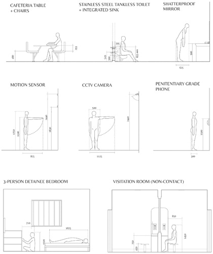
Figure 7. Plan of a solitary confinement cell (left); plan of an isolation area in the Laval IHC (right). The minimum dimensions for a cell in a correctional institution is 6.5 m2, while the minimum dimension for a solitary confinement “room” in the detention center is 7 m2, only half a square meter larger. Notably, the design of a solitary confinement room at the IHC is closer to a standard maximum-security cell than even to a medium-security cell. Furthermore, in federal guidelines, minimum-security cells are drawn with a separate toilet and sink, both made from ceramic materials, whereas the maximum-security cell is drawn with a stainless steel toilet-integrated-sink. The design language of this fixture is distinguishably carceral. (Plans drawn by author. Plan of solitary confinement cell adapted from “Federal Correctional Facilities Accommodations Guidelines 2015”; plan of isolation area adapted from “1.3 Plans” from “Schematic Design Report,” 2017.]
![Figure 7. Plan of a solitary confinement cell (left); plan of an isolation area in the Laval IHC (right). The minimum dimensions for a cell in a correctional institution is 6.5 m2, while the minimum dimension for a solitary confinement “room” in the detention center is 7 m2, only half a square meter larger. Notably, the design of a solitary confinement room at the IHC is closer to a standard maximum-security cell than even to a medium-security cell. Furthermore, in federal guidelines, minimum-security cells are drawn with a separate toilet and sink, both made from ceramic materials, whereas the maximum-security cell is drawn with a stainless steel toilet-integrated-sink. The design language of this fixture is distinguishably carceral. (Plans drawn by author. Plan of solitary confinement cell adapted from “Federal Correctional Facilities Accommodations Guidelines 2015”; plan of isolation area adapted from “1.3 Plans” from “Schematic Design Report,” 2017.]](/cms/asset/bec042a0-b596-4ee3-8c29-ddb9ab262aec/rjae_a_1790939_f0007_b.jpg)
Figure 8. The 1:10 Model of Hallway. The physicality of the object of the model becomes evident when placed within another space, as the entire model measures approximately 6 m long. Although conspicuous in size, the exterior of the model reads as a blind box, indistinguishable until approached and peered into. (Photograph by author.)
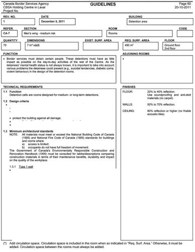
Figure 9. Redacted room space guidelines for a solitary confinement room. This information was used to select materials for the model reconstruction. (Room space guidelines from Access to Information Request A-2019-00781.)
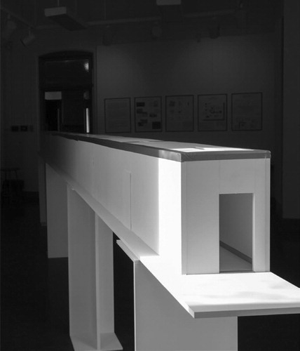
Figure 10. Solitary confinement room, fixtures, and manufacturers. Furniture is drawn based on CORCAN online catalogs, a manufacturer and construction service provider operated by Canadian Correctional Services, which employs the labor of existing and previously incarcerated people. (Drawing by author.)
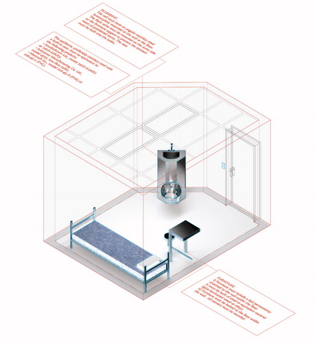
Figure 11. Still from a video of a 1:10 model of a detainee accommodation room, compared to the drawing of the space as reconstructed from room space guidelines. Each accommodation unit is installed with a color television, and all furniture is penitentiary grade to mitigate self-harm. The furniture was reconstructed based on dimensions and images of CORCAN furnishings. (Drawing and photograph by author.)
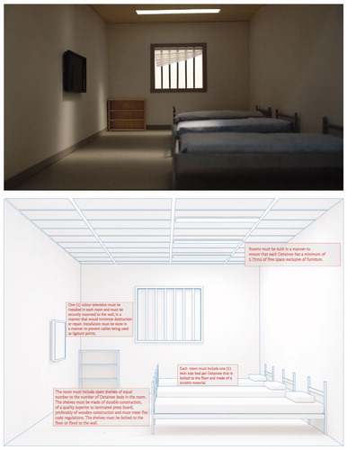
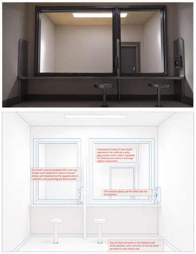
Figure 12. Drawing of a noncontact visitation room as reconstructed from the room space guidelines and annotated with the guidelines’ text, along with the corresponding model built from the plan in a schematic design report and its accompanying room space guidelines. (Drawing and photograph by author.)