Figures & data
Figure 1. Forelock bolt with wedge and ring (adapted based on McCarthy, Citation2005, fig. 42, p. 70. Reproduced with permission).
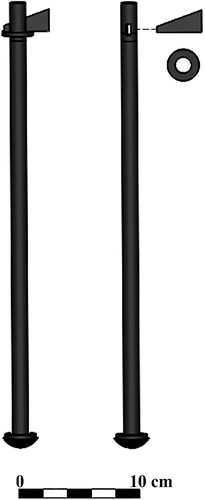
Figure 2. The manufacture of the forelock bolt: a) the bolt is measured; b) a cold chisel mark is made on the bolt; c) a hole is punched with a rectangular punch d) the bolt is cut off near the hole; e) the forelock is inserted and twisted to lock it in place (Light, Citation2000, p. 332, fig. 6. Reproduced with permission).
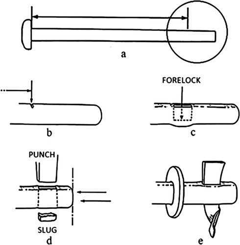
Figure 3. Comparing preloads of a threaded bolt to the forelock bolt: a) modern threaded bolt; b) forelock bolt. Fi = preload; P = external load; Ps = shear load; FI = impact force on the forelock; and τ = torque (illustration: N. Helfman).
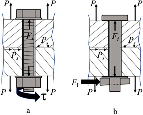
Figure 4. Schematic forelock installation of Serçe Limanı ship (illustration: N. Helfman).
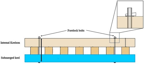
Figure 5. a) I-beam; b) Serçe Limanı section of keel-frames-keelson assemblage (illustration: N. Helfman).
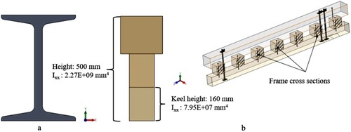
Figure 6. Transparent keelson-frames-keel section demonstrating preload induced by secured forelock bolt (illustration: N. Helfman).
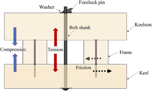
Figure 7. Radially dissipating preload: a) Preload generated from conventional nut and bolt configuration (Denkert et al., Citation2019, fig. 1, p. 2); b) Serçe Limanı between-frame forelock bolt configuration showing reduction of potential preload (illustration: N. Helfman).
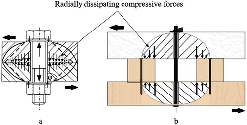
Figure 8. Generic preload stress-strain diagram for bolt materials: Sp = proof strength; Sy = yield strength; Sut = tensile strength (adapted from Shigley et al., 2004, fig. 8–13, p. 312).
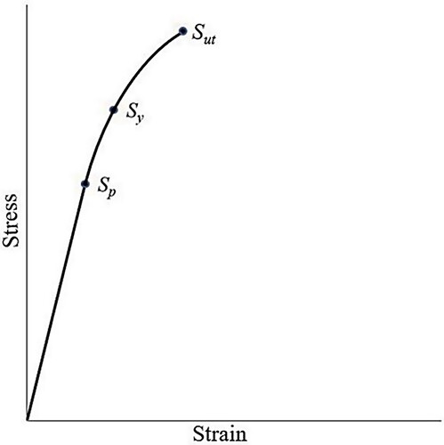
Figure 9. Generic wedge forces diagram where Nn = normal force, P = force applied, fn = friction forces, μ = friction coefficient, and θ = angle of inclination (illustration: N. Helfman).
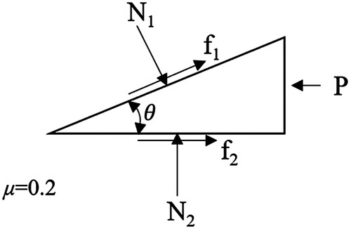
Figure 10. Forelock bolt mechanism: a) before wedge insertion; b) after insertion (illustration: N. Helfman).
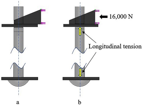
Figure 11. Displacement (δ) of shank of forelock bolt: a) probe points on shank vs. displacement results; b) displacement distribution representation (illustration: N. Helfman).
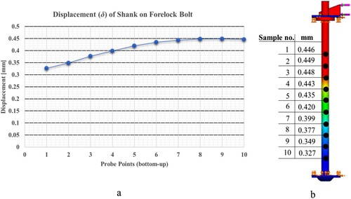
Figure 12. Strain – the ratio of the elongation change to the original length (illustration: N. Helfman).
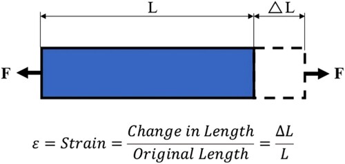
Figure 13. Generic illustration of forelock bolt validation model (illustration: N. Helfman).
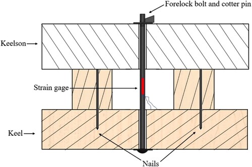
Table 1. Dimensions of experimental samples (Mathews & Steffy, Citation2004).
Figure 14. Wrought iron nail manufactured for laboratory experimentation (photo: N. Helfman).
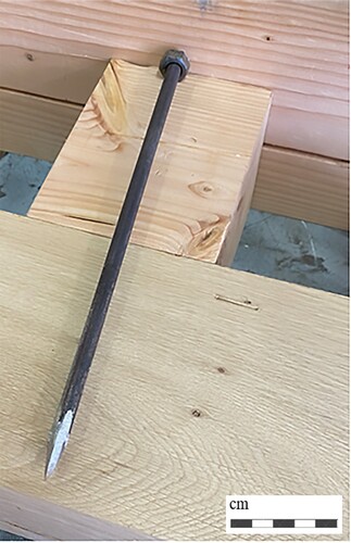
Table 2. Averaged mechanical properties of elm and oak species for bending and transverse stresses perpendicular (radial) to the grain (Ross, Citation2010).
Figure 15. a) Replication of impact on the forelock of the bolt wedge protruding from the keelson; b) detail of the bolt fitted with a strain gage (photos: N. Helfman).
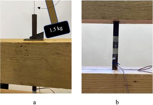
Figure 16. Comparing strain results between FEA simulations and laboratory trials (Authors).
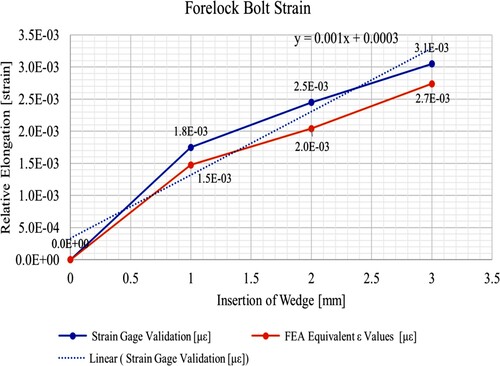
Table 3. FEA elongation (δ) and strain (ϵ) compared to validation strain values.
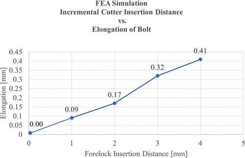
Figure 17. FEA simulation of the incremental insertion of the forelock versus elongation of the bolt (Authors).