Figures & data
Figure 1. Illustration of the domains used in the different simulations: (a) Simulation based on the Lund method, (b) Simulation based on the DFSEM and the DFM.
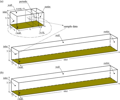
Figure 2. Simulation of the recycling and rescaling method.
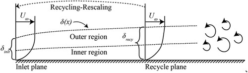
Table 1. Turbulent length scales applied at the inlet boundary together with DFM.
Table 2. Turbulent length scales applied at the inlet boundary together with SEM or DFSEM.
Table 3. Summary of the mesh configurations.
Table 4. Mesh configurations for different mesh size.
Table 5. Summary of the inflow boundary conditions.
Table 6. Inlet turbulent length scales applied in the simulation.
Figure 3. The profiles of the turbulent kinetic energy spectrum of the simulation based on DFM with different input turbulent length scales at the same vertical position where and distinctive horizontal positions where (a)
(b)
(c)
(d)
(e)
.
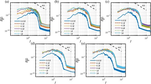
Figure 4. The profiles of friction velocity along the streamwise direction based on DFM with different input turbulent length scale.
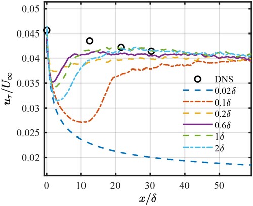
Figure 5. Distribution of the mean velocity profiles of simulations based on DFM with different input turbulent length scales at different positions: (a) x = inlet (b) (c)
(d)
(e)
(f)
.
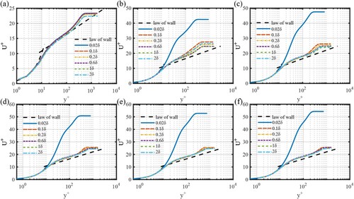
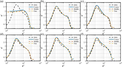
Figure 6. Distribution of the streamwise fluctuating velocity profiles of simulations based on DFM with different input turbulent length scales at different positions: (a) x = inlet (b) (c)
(d)
(e)
(f)
.
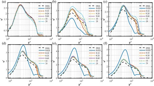
Figure 7. Distribution of the vertical fluctuating velocity profiles of simulations based on DFM with different input turbulent length scales at different positions: (a) x = inlet (b) (c)
(d)
(e)
(f)
.
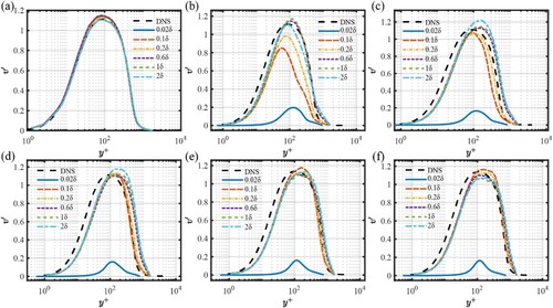
Figure 8. Distribution of the spanwise fluctuating velocity profiles of simulations based on DFM with different input turbulent length scales at different positions: (a) x = inlet (b) (c)
(d)
(e)
(f)
.
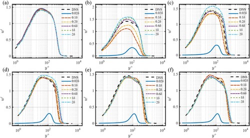
Figure 9. Distribution of the Reynolds shear stresses profiles of simulations based on DFM with different input turbulent length scales at different positions: (a) x = inlet (b) (c)
(d)
(e)
(f)
.
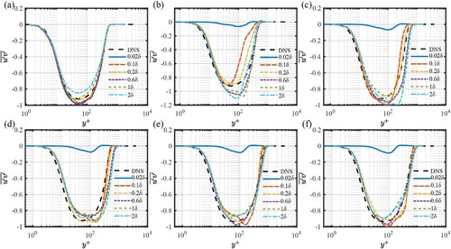
Figure 10. The profiles of the turbulent kinetic energy spectrum of the simulation based on DFSEM with different input turbulent length scales at the same vertical position where and distinctive horizontal positions where (a)
(b)
(c)
(d)
(e)
.
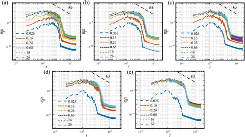
Figure 11. The profiles of friction velocity along the streamwise direction based on DFSEM with different input turbulent length scale.
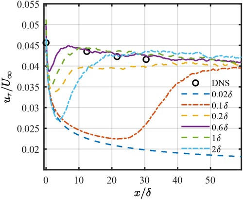
Figure 12. Distribution of the mean velocity profiles of simulations based on DFM with different input turbulent length scales at different positions: (a) x = inlet (b) (c)
(d)
(e)
(f)
.
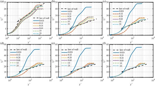
Figure 13. Distribution of the streamwise fluctuating velocity profiles of simulations based on DFSEM with different input turbulent length scales at different positions: (a) x = inlet (b) (c)
(d)
(e)
(f)
.

Figure 14. Distribution of the vertical fluctuating velocity profiles of simulations based on DFSEM with different input turbulent length scales at different positions: (a) x = inlet (b) (c)
(d)
(e)
(f)
.
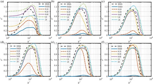
Figure 15. Distribution of the spanwise fluctuating velocity profiles of simulations based on DFSEM with different input turbulent length scales at different positions: (a) x = inlet (b) (c)
(d)
(e)
(f)
.
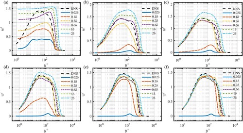
Figure 16. Distribution of the turbulent shear stresses profiles of simulations based on DFSEM with different input turbulent length scales at different positions: (a) x = inlet (b) (c)
(d)
(e)
(f)
.
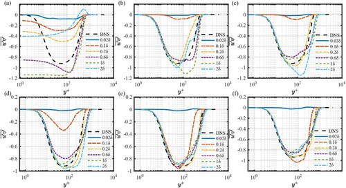
Figure 17. Distribution of the mean velocity profiles of simulations based on Lund with different length of the precursor domain: (a) x = inlet (b) (c)
(d)
(e)
(f)
.
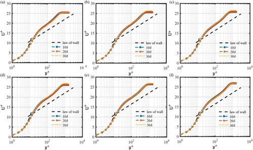
Figure 18. Distribution of the turbulent Reynolds stresses profiles of simulations based on Lund with different length of the precursor domain at: (a) x = inlet (b) (c)
(d)
(e)
(f)
.
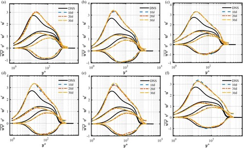
Figure 19. Distribution of the TKE budget terms profiles of simulations based on Lund with different length of the precursor domain at: (a) x = inlet (b) (c)
(d)
(e)
(f)
.
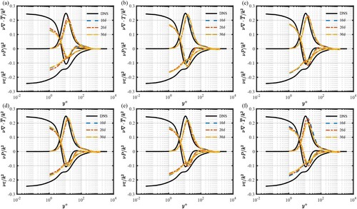
Figure 20. Instantaneous velocity field (a-c) and the corresponding iso-surface of in the x-y plane of different cases using the (a) DFSEM, (b) DFM, and (c) Lund method. Instantaneous velocity field (d-f) and the corresponding iso-surface of
in the y-z plane (at the inlet) of different cases using the (d) DFSEM, (e) DFM, and (f) Lund method.
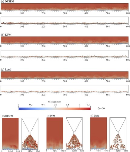
Figure 21. Distribution of the mean velocity profiles of simulations based on different IBC methods at different positions: (a) at x = inlet (b) at (c)
(d)
(e)
(f)
.
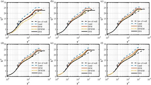
Figure 22. The profiles of friction velocity along the streamwise direction based on DFM with different input turbulent length scale.
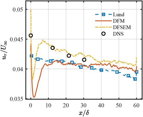
Figure 23. Distribution of the turbulent Reynolds stresses of simulations based on different IBC methods at different positions: (a) at x = inlet (b) at (c)
(d)
(e)
(f)
.
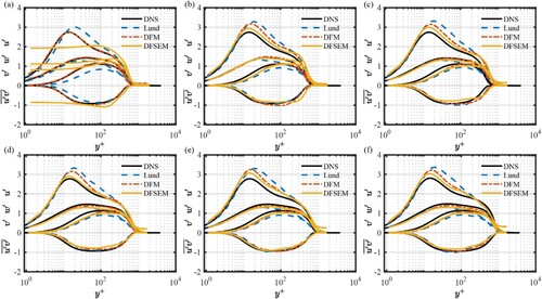
Figure 24. The profiles of the production of simulations based on different IBC methods at different downstream positions: (a) at x = inlet (b) at (c)
(d)
(e)
(f)
.
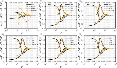
Figure A1. Distribution of the mean velocity profiles of simulations based on DFSEM with different mesh size at different positions: (a) at x = inlet (b) at (c)
(d)
(e)
(f)
.
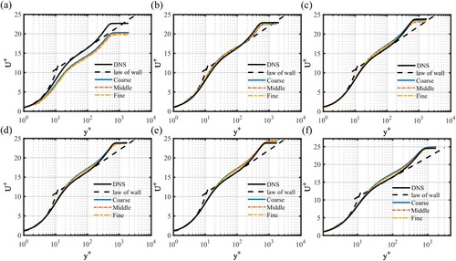
Figure A2. Distribution of the profiles of Reynolds stresses component in simulations based on DFSEM with different mesh size at different positions: (a) at x = inlet (b) at
(c)
(d)
(e)
(f)
.