2,225
Views
101
CrossRef citations to date
0
Altmetric
Original Articles

Radioiodine Biogeochemistry and Prevalence in Groundwater

, , , , , , , , & show all
Pages 2287-2335 | Published online: 11 Aug 2014

Figures & data

FIGURE 1. Relative total activity emitted as a function of time after the Chernobyl accident. Note that 131I accounted for much of the radiation during the first week (redrawn from IAEA, 2006).

TABLE 1. Inventory of radioiodine isotopes produced in a representative material irradiated by a production reactor (Kantelo et al., Citation1990)

TABLE 2. Radiochemical properties of 129I and 131I

TABLE 3. Major sources of 129I in the environment (compiled from Raisbeck and Yiou, Citation1999)

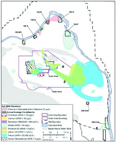
FIGURE 2. 129I plumes in the surface aquifer of the 200 East and 200 West Areas on the Hanford Site. 129I plumes coexist with other contaminants. 129I, 99Tc, and 3H are the primary risk drivers at the site (Department of Energy, 2012b).
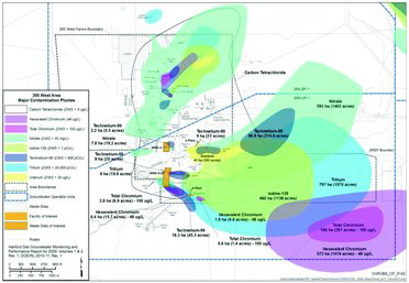
FIGURE 3. Groundwater plume map in the 200 West Area (including 200-UP-1 and 200-ZP-1 Operable Units). The plumes primarily emanate from disposal cribs located near U Plant and S Plant (Department of Energy, 2012b).
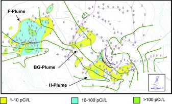
FIGURE 4. 129I plume map of F-Area, H-Area, and Burial Ground (BG) plumes on the Savannah River Site; green lines are contours of water table potentiometric surface, blue dots with numbers are monitoring wells.

TABLE 4. Reactions of log K association constants of selected aqueous species of iodine

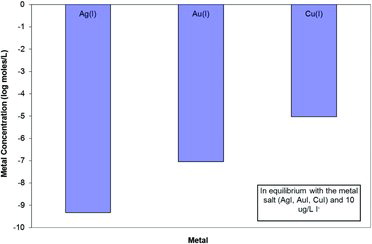
FIGURE 5. Solubility of various metal iodides expressed as the aqueous metal concentration (log mol/L) at 10 μg/L iodide.
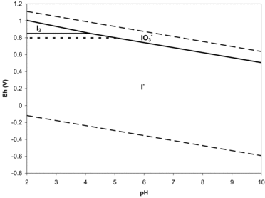
FIGURE 6. Eh-pH diagram of aqueous iodine speciation; solid line = total iodine concentration of 1 μg/L, a typical groundwater concentration, dotted line = total iodine concentration of 58 μg/L, a typical seawater concentration (Fuge and Johnson, Citation1986); dashed lines are stability limits of water (note that organo-iodine species are not included in these calculations).

TABLE 5. Stable 127I and radioactive 129I speciation in groundwater collected in March 2012 from 200 West Area (Santschi et al., Citation2012)

TABLE 6. Iodide and iodate Kd values after 21 days of composite sediments recovered from 200 West Area borehole cores (Santschi et al., Citation2012)
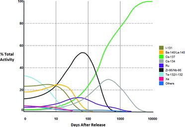
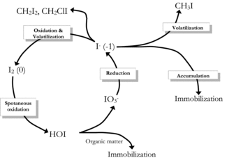
FIGURE 7. Biological transformations of iodine (Amachi et al., Citation2005a).
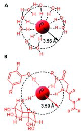
FIGURE 8. Iodide surrounded by (A) Aqueous hydration shell; (B) intracellular phenols, carbohydrates, or amines (Küpper et al., Citation2008).