Figures & data
Figure 1. Concept and basic design principles for HEAs. (a) Typical contour of ΔSmix for a ternary alloy system. The corner regions with lower ΔSmix, indicating traditional alloys (Tas) based on one or two principal elements while the centre region with higher ΔSmix, indicating the equimolar ternary HEAs. (b) Plots ΔHmix as a function of δ, guiding the phase selection of HEAs. (c) Plots of Ω as a function of δ, guiding the phase selection of HEAs. (d) Plots of VEC as a function of ϕ for the phase selection of HEAs. Partly reproduced from Ref. 3 © 2016 Elsevier.
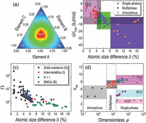
Figure 2. B-doping-induced enhancement tensile properties of HEA at cryogenic temperatures. (a) Comparison of stress-strain curves between B-doped and undoped nonequiatomic FeMnCoCr HEAs at different temperatures, (b) Comparison of stress-strain curves between B-doped and undoped NiFeMnCoCr HEAs with varied grain sizes at 77 K, and (c) Plots of yield strengths as a function of elongations for B-doped and undoped HEAs under tensile load at 77 K. Those of austenitic steel, stainless steels and single-phase HEAs/MEAs are also plotted for comparisons. Reproduced from Ref. 25 © 2020 Elsevier.
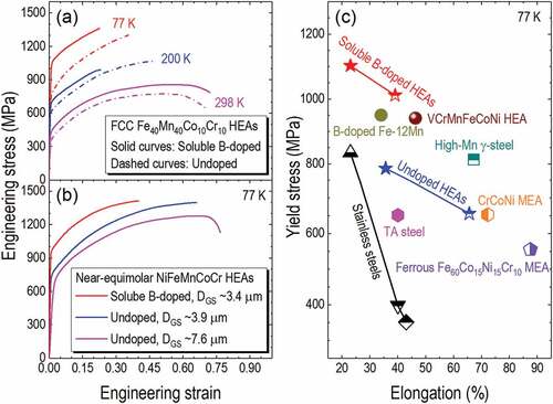
Table 1. Characteristic comparisons of a few typical HEAs (i.e. Al20Li20Mg10Sc20Ti30, low-density refractory CrNbTiVZr, CrMnFeCoNi) and tradictional alloys (see ref. 1 and references therein).
Figure 3. Schematic showing typical laser cladding of metal alloys on metal substrate. (a) Direction deposition using powder feedstock, (b) Direction deposition using wire feedstock and (c) Laser fussion of prelaied powders on substrate. (d) Typical SEM image recorded from the cross-section of cladding path, showing the coating with substrate dilution, i.e. due to the surface melting of the substrate.
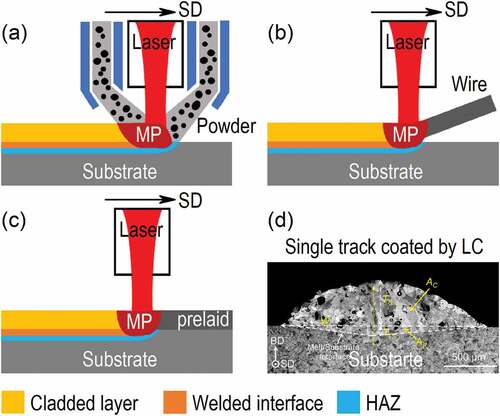
Figure 4. Laser cladding of TiC particles reinforced HEA coatings either by incorporating TiC particles into AlCoCrCuFe HEA powder feedstock or by in situ synthesis of TiC particles from elemental Ti and C incorporated in CoCrCuFeNiSi0.2 HEA powder feedstock. (a) AlCoCrCuFe-0TiC, (b) AlCoCrCuFe-10 wt.% TiC, (c) AlCoCrCuFe- 30 wt.% TiC, (d) AlCoCrCuFe-50 wt.% TiC, (e) CoCrCuFeNiSi0.2-(Ti, C)0, (f) CoCrCuFeNiSi0.2-(Ti, C)0.5, (g) CoCrCuFeNiSi0.2-(Ti, C)1.0 and (h) CoCrCuFeNiSi0.2-(Ti, C)1.5. (i)-(l) Schematics showing the in situ synthesis of TiC particles and the TiC particles reinforced dendritic HEA structures within a cladding path. Partly reproduced from Refs. 47 and 50 © 2020 Elsevier.
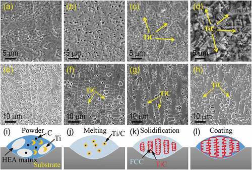
Table 2. Summary of typical HEA coatings and their characteritics produced by LC on metal and alloy substrates.
Figure 5. Various application areas of LC-HEAs.