Figures & data
Figure 1. (a) the molecular structure schematic diagram of P(VDF-co-HFP)/MXene’s synthetic composition. (b) schematic diagram of PM-TENG’s structure. (c) the SEM image of P(VDF-co-HFP)/MXene film surface. (d) the physical picture of PM-TENG device. (e) XRD analysis of P(VDF-co-HFP) under different MXene contents. (f) XPS spectrum of P(VDF-co-HFP) composite material with 10% MXene.
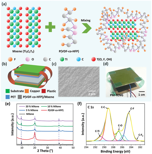
Figure 2. (a) structural diagram of PM-TENG working principle. (b, c) the relationship between output voltage/transfer charge of PM-TENG and separation distance simulated by using COMSOL software. (d) the simulated voltage of PM-TENG under different thickness triboelectric layer. (e, f) the P(VDF-co-HFP)/MXene polymer dielectric constant. (g) the formation of microcapacitors and conducting channels.
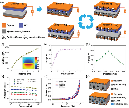
Figure 3. (a–c) the electrical output of four TENGs based on PVDF@PET, PVDF/MXene@PET, P(VDF-co-HFP(10%))/MXene@PET, and P(VDF-co-HFP(10%))/MXene@PET. The (d) Voc, (e) Jsc, and (f) Qsc of PM-TENG. The output signal of (f) Voc and (g) Jsc of PM-TENG. (h) the influence of MXene content on the output performance of PM-TENG device.
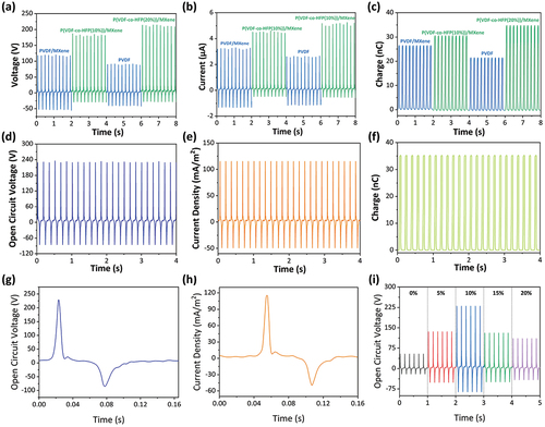
Figure 4. (a) the influence of MXene content on the Qsc of PM-TENG. (b) the influence of P(VDF-co-HFP)/MXene film thickness on Voc of PM-TENG. (c, d) the influence of working frequency on Voc and Jsc of PM-TENG device. (e) the influence of external force on Voc of PM-TENG device.
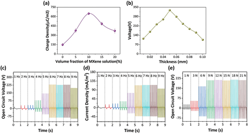
Figure 5. (a, b) the dependence of output (voltage, current, power) of PM-TENG on different resistances. (c) the output voltage signal of PM-TENG with a match load of 4 MΩ. (d, e) stability testing for long-term work of PM-TENG. (f) the charging/discharging curves of a 24 μF capacitor for powering the humidity/temperature sensor driven by PM-TENG device.
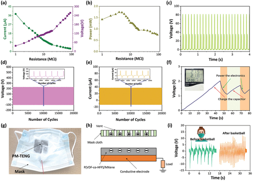
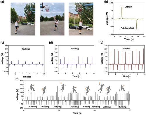
Figure 6. (a1-a3) Photos of athletes doing shooting sports. (b) The output signal of PM-TENG installed inside the shoe. (c-e) The PM-TENG voltage output signal under various motion posture. (f) Sensing signals of PM-TENG under basketball players in continuous motion