263
Views
24
CrossRef citations to date
0
Altmetric
Original Articles

Design of radiant enclosures using inverse and non-linear programming techniques

, &
Pages 541-560 | Received 02 Oct 2002, Accepted 12 Dec 2002, Published online: 13 May 2010

Figures & data

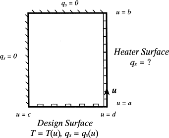
FIGURE 1 Boundary conditions for different design methodologies: (a) forward; (b) inverse; (c) optimization.
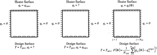
FIGURE 1 Boundary conditions for different design methodologies: (a) forward; (b) inverse; (c) optimization.

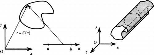
FIGURE 2 Parametric representation of the enclosure geometry.

FIGURE 2 Parametric representation of the enclosure geometry.

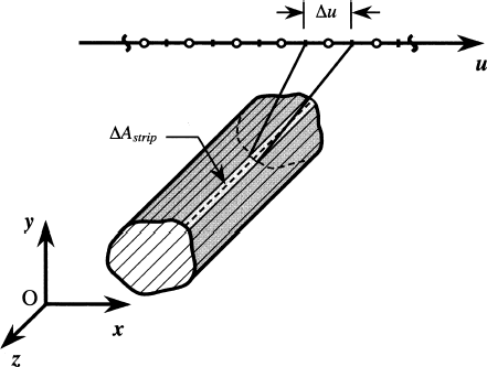
FIGURE 3 Discretization of the enclosure surface.

FIGURE 3 Discretization of the enclosure surface.

FIGURE 4 Example of an inverse radiant enclosure problem.

FIGURE 4 Example of an inverse radiant enclosure problem.

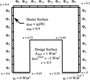
FIGURE 5 Radiant enclosure design problem.

FIGURE 5 Radiant enclosure design problem.

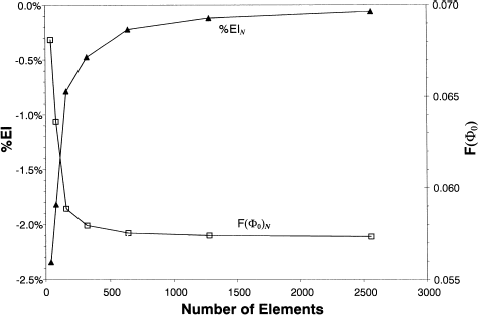
FIGURE 6 Grid refinement study.

FIGURE 6 Grid refinement study.

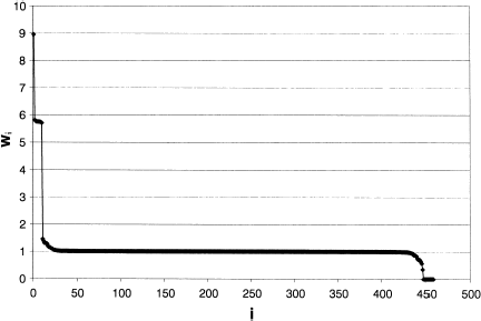
FIGURE 7 Singular values found by decomposing the A matrix.

FIGURE 7 Singular values found by decomposing the A matrix.

FIGURE 8 Distribution of q s (u) and E b (u) over the heater surface, found using p = 460 singular values.
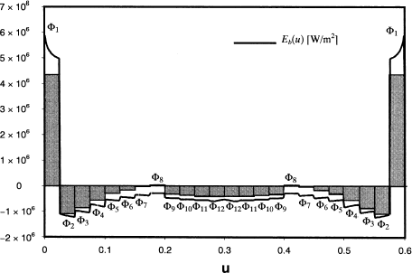
FIGURE 8 Distribution of q s (u) and E b (u) over the heater surface, found using p = 460 singular values.

FIGURE 9 Distribution of q s (u) and E b (u) over the heater surface, found using p = 449 singular values.
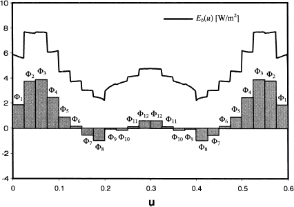
FIGURE 9 Distribution of q s (u) and E b (u) over the heater surface, found using p = 449 singular values.

FIGURE 10 Distribution of q s (u) and E b (u) over the heater surface, found using p = 448 singular values.
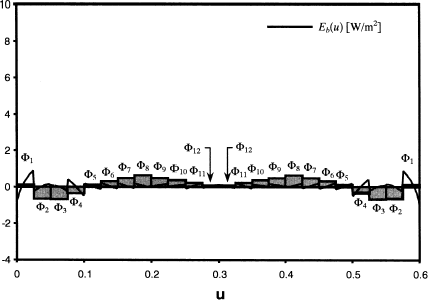
FIGURE 10 Distribution of q s (u) and E b (u) over the heater surface, found using p = 448 singular values.

TABLE I Heater settings corresponding to [W/m2]

TABLE II Values of || x ||2 and || δ ||2 corresponding to

FIGURE 11 Distribution of q s (u) over the design surface, found by nullifying the negative heater settings of the p = 449 solution.
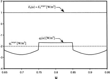
FIGURE 11 Distribution of q s (u) over the design surface, found by nullifying the negative heater settings of the p = 449 solution.

FIGURE 12 Heater settings found by minimizing the non-regularized objective function, Eq. (Equation17).
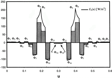
FIGURE 12 Heater settings found by minimizing the non-regularized objective function, Eq. (Equation17).

FIGURE 14 Distribution of q s (u) over the design surface, found by minimizing non-regularized and regularized objective functions.
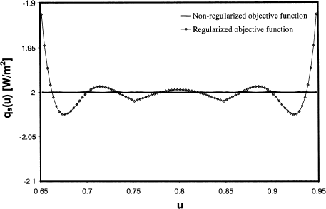
FIGURE 14 Distribution of q s (u) over the design surface, found by minimizing non-regularized and regularized objective functions.

TABLE III Optimal heater settings for the regularized and non-regularized objective functions [W/m2]

FIGURE 13 Heater settings found by minimizing the regularized objective function, Eq. (Equation32).
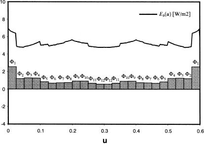
FIGURE 13 Heater settings found by minimizing the regularized objective function, Eq. (Equation32).

Reprints and Corporate Permissions

Please note: Selecting permissions does not provide access to the full text of the article, please see our help page How do I view content?

To request a reprint or corporate permissions for this article, please click on the relevant link below:

Academic Permissions

Please note: Selecting permissions does not provide access to the full text of the article, please see our help page How do I view content?

Obtain permissions instantly via Rightslink by clicking on the button below:

If you are unable to obtain permissions via Rightslink, please complete and submit this Permissions form. For more information, please visit our Permissions help page.