Figures & data
Figure 1. Equivalent circuit of epoxy thermoset.
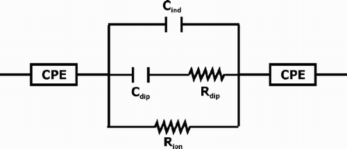
Figure 2. Real and imaginary impedance spectra typical of a particular given state in epoxy resin cure. The equivalent circuit used is shown in and the circuit element values are given in .
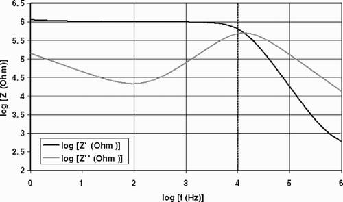
Table 1. Circuit element values for the construction of simulated spectra.
Table 2. Sensitivity to circuit parameters expressed as the average percentage difference from the original case for a ±10% change in the parameter.
Figure 3. Genetic algorithm flowchart.
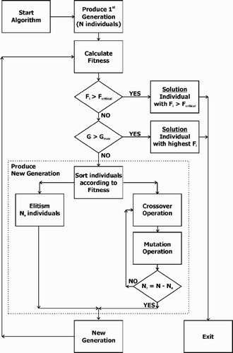
Table 3. Objective functions tested without any regularization term.
Table 4. Search space of the fitting parameters.
Table 5. Fitting results for the tuning of the genetic algorithm parameters.
Table 6. Final values for the genetic algorithm implementation.
Table 7. Results from test runs on noisy data for the determination of the objective function.
Figure 4. Impedance spectrum with 4 outliers (indicated by crosses at log[ f (Hz)] = 0, 1.5, 1.75 and 2) and 10% random Gaussian noise. The continuous lines are noiseless spectra (same as ).
![Figure 4. Impedance spectrum with 4 outliers (indicated by crosses at log[ f (Hz)] = 0, 1.5, 1.75 and 2) and 10% random Gaussian noise. The continuous lines are noiseless spectra (same as Fig. 2).](/cms/asset/3314c949-8975-40b0-a56f-0edcfeee61f4/gipe_a_10050474_o_fig004g.gif)
Figure 5. Dependence of circuit parameters on the regularization parameter. The fitted spectrum is shown in . The correct values are denoted by the grey line.
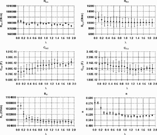
Figure 6. Geometry of GIA dielectric sensor.
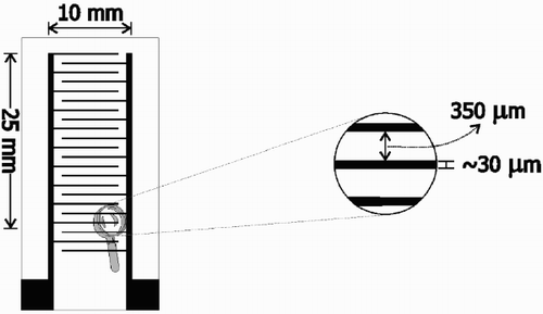
Figure 7. Real impedance spectrum evolution for the isothermal cure of RTM6 at 150°C.
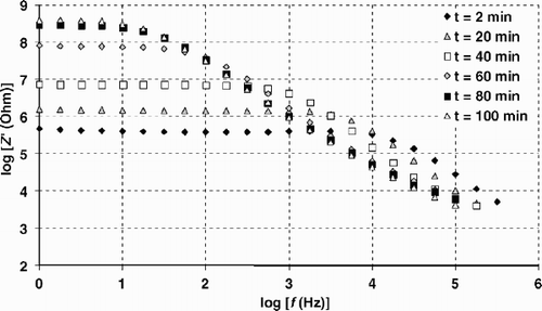
Figure 8. Imaginary impedance spectrum evolution for the isothermal cure of RTM6 at 150°C.
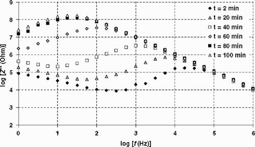
Figure 9. Methodology for modelling consecutive spectra.
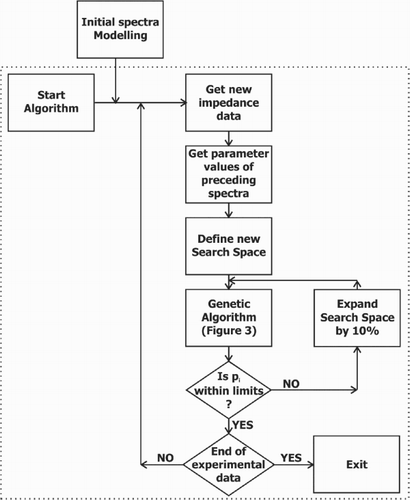
Table 8. Adaptive search space of the fitting parameters. Subscript p denotes the parameter values obtained from fitting the chronologically preceding spectrum.
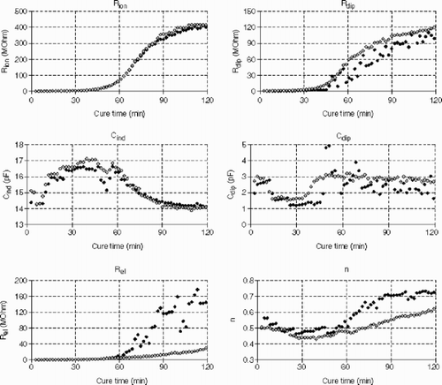
Figure 10. Equivalent circuit parameters for the isothermal cure of RTM6 at 150°C. Black points show the fitting without regularization. Grey points show the fitting when the regularization term is added to the objective function.