Figures & data
Figure 1. Annual number of labour accidents during construction works.
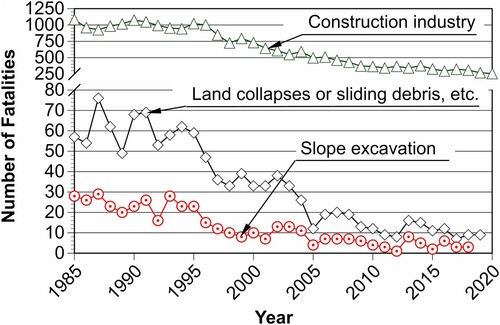
Figure 2. Relationship between slope failure risk and working items during the construction process of a retaining wall.
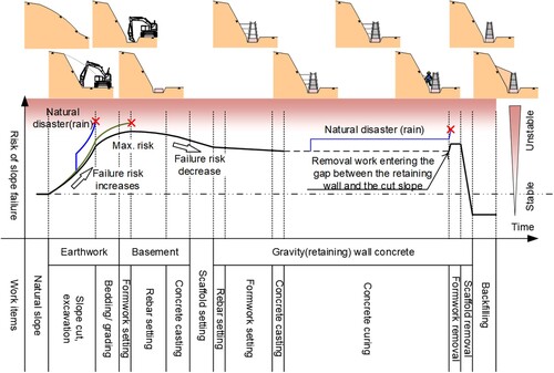
Figure 3. Number of personnel present at the time of accident [Citation23].
![Figure 3. Number of personnel present at the time of accident [Citation23].](/cms/asset/4b46d48e-0717-49da-be90-5a25755102f6/tose_a_2356350_f0003_oc.jpg)
Figure 4. Classification of slope failure accidents by construction methods [Citation23].
![Figure 4. Classification of slope failure accidents by construction methods [Citation23].](/cms/asset/b8c63c61-bc2b-43e8-af91-66e8636fd3af/tose_a_2356350_f0004_oc.jpg)
Figure 5. Accident site of concrete frame construction work [Citation25].
![Figure 5. Accident site of concrete frame construction work [Citation25].](/cms/asset/df41d3be-793f-4133-b483-b1e3b94c74d2/tose_a_2356350_f0005_oc.jpg)
Figure 6. Accident site of frame dismantling work [Citation25].
![Figure 6. Accident site of frame dismantling work [Citation25].](/cms/asset/def5bf08-3e2d-480d-8f68-4ea87a1fbd4b/tose_a_2356350_f0006_oc.jpg)
Figure 7. Classification of slope failure accident causes of death [Citation23].
![Figure 7. Classification of slope failure accident causes of death [Citation23].](/cms/asset/b845d459-a107-4eb1-a331-5e09ba812ea3/tose_a_2356350_f0007_oc.jpg)
Table 1. Design and construction procedures checklist [Citation27].
Table 2. Daily checklist [Citation27].
Figure 8. Field site before disaster restoration work.
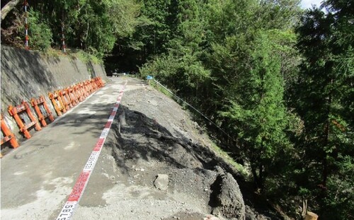
Figure 9. Plane view of the field site.
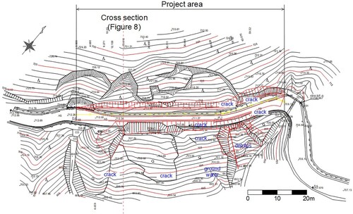
Figure 10. Typical cross-section of the slope and geometry.
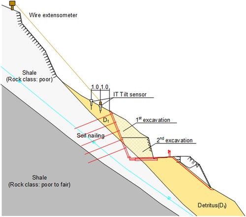
Figure 11. Cracks found in the retaining wall before construction.
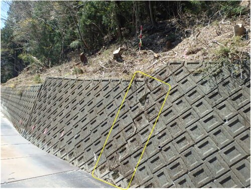
Figure 12. Small collapses caused by groundwater during excavation.
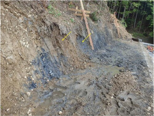
Table 3. Design and construction procedures checklist at this field site.
Figure 13. Installation of measurement instrumentation on the site.
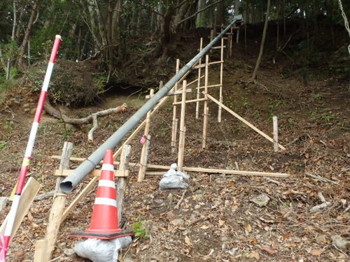
Figure 14. IT tilt sensor (AKEBONO Brake Industry Co., Ltd., Japan): (a) general appearance; (b) tilt sensor installed in the ground.
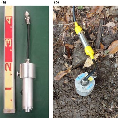
Table 4. Excavation and nailing phases during this construction.
Figure 15. Time histories of two tilt sensors including some main events: excavation, nailing, rainfall, etc.
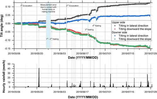
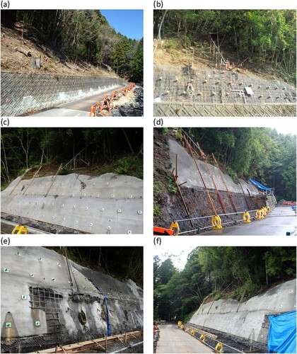
Figure 16. During and before the construction at the field monitoring site: (a) before work; (b) after first excavation; (c) after first and second nailing works; (d) after second excavation; (e) third nailing after rain; (f) finished nailing works.