479
Views
7
CrossRef citations to date
0
Altmetric
Technical Papers

Assessment of a regulatory model's performance relative to large spatial heterogeneity in observed ozone in Houston, Texas

, , &
Pages 696-706 | Published online: 24 May 2012

Figures & data

Figure 1. Distributions of observed daily maximum 1-hr (left) and 8-hr (right) O3 concentrations at all regulatory monitors from 2000 to 2009. The data are separated into typical and non-typical days. A typical O3 change day has observed 1-hr changes in O3 concentration of less than 40 ppb, or 2-hr changes less than 60 ppb. A non-typical O3 change day has a 1-hr change of at least 40 ppb, or a 2-hr change of at least 60 ppb. The 25th, 50th, and 75th percentile concentrations are represented by the box bottom, middle, and top.
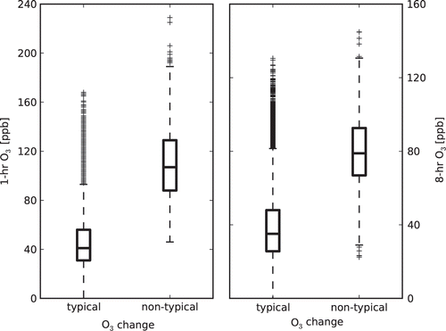
Figure 1. Distributions of observed daily maximum 1-hr (left) and 8-hr (right) O3 concentrations at all regulatory monitors from 2000 to 2009. The data are separated into typical and non-typical days. A typical O3 change day has observed 1-hr changes in O3 concentration of less than 40 ppb, or 2-hr changes less than 60 ppb. A non-typical O3 change day has a 1-hr change of at least 40 ppb, or a 2-hr change of at least 60 ppb. The 25th, 50th, and 75th percentile concentrations are represented by the box bottom, middle, and top.

Figure 2. Distributions of observed daily maximum 8-hr O3 concentrations at all regulatory monitors from 2000 to 2009. Only measurement data from May to October are shown (n = 46,000 monitors-days). The black columns are daily maximum 8-hr O3 concentrations that were measured on days that had a non-typical O3 change (NTOC), i.e., an observed O3 change of at least 40 ppb/hr, or 60 ppb/2 hr (n = 916 monitors-days). The gray columns are 8-hr O3 concentrations that did not include an observed NTOC (n = 45,084 monitors-days).
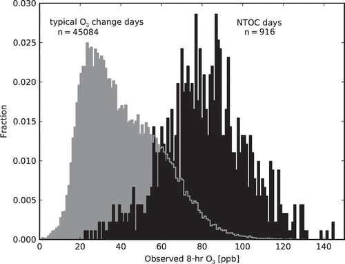
Figure 2. Distributions of observed daily maximum 8-hr O3 concentrations at all regulatory monitors from 2000 to 2009. Only measurement data from May to October are shown (n = 46,000 monitors-days). The black columns are daily maximum 8-hr O3 concentrations that were measured on days that had a non-typical O3 change (NTOC), i.e., an observed O3 change of at least 40 ppb/hr, or 60 ppb/2 hr (n = 916 monitors-days). The gray columns are 8-hr O3 concentrations that did not include an observed NTOC (n = 45,084 monitors-days).

Figure 3. The location of the 25 regulatory air quality monitors used in this study. Plot (a) shows 10 years of measurements spanning 2000–2009. For those monitors that came online after 2000, data collection began on the deployment date and continued through 2009. For this time period, the inner shaded circle shows the monitors at which 60% of all non-typical O3 changes (NTOCs) were observed. The outer shaded circle covers the monitors at which 90% of all NTOCs were observed. Both circles are centered on the ship channel. Plot (b) shows the grid cell location and frequency of simulated NTOCs by the base case simulation in the 2-km modeling domain for the entire 120-day modeling episode. (Color figure available online).
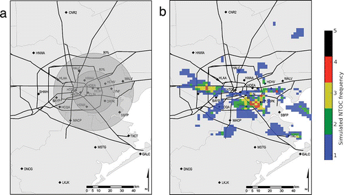
Figure 3. The location of the 25 regulatory air quality monitors used in this study. Plot (a) shows 10 years of measurements spanning 2000–2009. For those monitors that came online after 2000, data collection began on the deployment date and continued through 2009. For this time period, the inner shaded circle shows the monitors at which 60% of all non-typical O3 changes (NTOCs) were observed. The outer shaded circle covers the monitors at which 90% of all NTOCs were observed. Both circles are centered on the ship channel. Plot (b) shows the grid cell location and frequency of simulated NTOCs by the base case simulation in the 2-km modeling domain for the entire 120-day modeling episode. (Color figure available online).

Figure 4. Comparison of base case and baseline hourly point source HRVOC emissions. The main plot shows hourly emission rates for the subset of point sources that are included in both inventories (not all point sources are included in both inventories). Each data point directly compares the rate in the base case to that in the baseline at a particular time and location. The solid black line shows where the emission rates in the two emission inventories are equivalent. The inset plot shows distributions of hourly HRVOC emission rates at all point sources in either inventory. Though the inset is more inclusive than the main plot, it does not provide a direct hour-by-hour, source-by-source comparison of the two inventories. (Color figure available online).
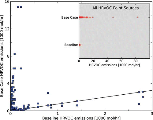
Figure 4. Comparison of base case and baseline hourly point source HRVOC emissions. The main plot shows hourly emission rates for the subset of point sources that are included in both inventories (not all point sources are included in both inventories). Each data point directly compares the rate in the base case to that in the baseline at a particular time and location. The solid black line shows where the emission rates in the two emission inventories are equivalent. The inset plot shows distributions of hourly HRVOC emission rates at all point sources in either inventory. Though the inset is more inclusive than the main plot, it does not provide a direct hour-by-hour, source-by-source comparison of the two inventories. (Color figure available online).

Table 1. Simulated maximum 1-hr and 2-hr O3 changes that met non-typical O3 change (NTOC) criteria at any grid cell in the 2-km domain using the model's base case and baseline emission inventories

Table 2. The 25 regulatory air quality monitors used in this study

Figure 5. Similar to , but limited to the days during the 120-day modeling episode for the base case simulation. Plot (a) shows distributions of observed daily maximum 8-hr O3 concentrations at all monitors for days that coincided with the modeling episode (n = 3000 monitors-days). The black columns are the concentrations that were measured on days that had a non-typical O3 change (NTOC), i.e., an observed O3 change of at least 40 ppb/hr, or 60 ppb/2 hr (n = 916 monitors-days). Plot (b) shows distributions of simulated daily maximum 8-hr O3 concentrations at all grid cells where the regulatory monitors are located (n = 2400 grid cell-days). Here, the black columns are concentrations that were predicted on days that had a simulated NTOC. Twenty-four modeling days had incomplete data and are excluded from this plot.
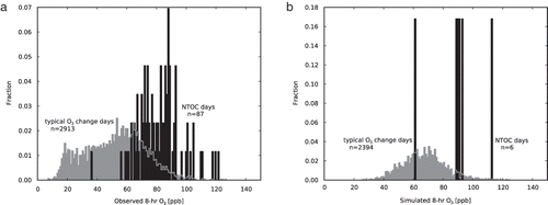
Figure 5. Similar to Figure 2, but limited to the days during the 120-day modeling episode for the base case simulation. Plot (a) shows distributions of observed daily maximum 8-hr O3 concentrations at all monitors for days that coincided with the modeling episode (n = 3000 monitors-days). The black columns are the concentrations that were measured on days that had a non-typical O3 change (NTOC), i.e., an observed O3 change of at least 40 ppb/hr, or 60 ppb/2 hr (n = 916 monitors-days). Plot (b) shows distributions of simulated daily maximum 8-hr O3 concentrations at all grid cells where the regulatory monitors are located (n = 2400 grid cell-days). Here, the black columns are concentrations that were predicted on days that had a simulated NTOC. Twenty-four modeling days had incomplete data and are excluded from this plot.

Figure 6. Spatial plot showing simulated 1-hr O3 differences at (a) 6:00 a.m. and (b) 8:00 a.m. on August 20, 2006. The values were obtained by subtracting the baseline O3 predictions from the base case O3 predictions. The location of the DRPK monitor is marked by a black diamond. An HRVOC emissions event occurred in the base case EI at 6:00 a.m. in the grid cell marked with a black “X.” (Color figure available online).
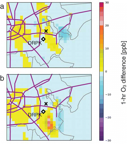
Figure 6. Spatial plot showing simulated 1-hr O3 differences at (a) 6:00 a.m. and (b) 8:00 a.m. on August 20, 2006. The values were obtained by subtracting the baseline O3 predictions from the base case O3 predictions. The location of the DRPK monitor is marked by a black diamond. An HRVOC emissions event occurred in the base case EI at 6:00 a.m. in the grid cell marked with a black “X.” (Color figure available online).

Figure 7. Observed and simulated 1-hr O3 concentrations on August 20, 2006, recorded at the DRPK monitor. Simulated O3 concentrations are nearly identical for both the base case and baseline simulations except for the 3 hr immediately following the HRVOC release (6:00 a.m.) in the base case simulation.
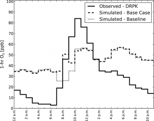
Figure 7. Observed and simulated 1-hr O3 concentrations on August 20, 2006, recorded at the DRPK monitor. Simulated O3 concentrations are nearly identical for both the base case and baseline simulations except for the 3 hr immediately following the HRVOC release (6:00 a.m.) in the base case simulation.

Figure 8. Spatial plot showing predictions from the base case simulation of 1-hr O3 concentrations at (a) 9:00 a.m., (b) 10:00 a.m., (c) 11:00 a.m., and (d) 12:00 p.m. on August 1, 2005. The diamond markers show measurement data from air quality monitors; if no data are available, the marker is a black dot. Color mismatches between the diamond markers (measurements) and grid cells (simulations) indicate model over- or underpredictions. Gray arrows show the simulated wind vectors at select grid cells. Arrows originating at the center of a diamond marker show measured wind data. Simulated NTOCs are marked with a black “X” (9:00 a.m. and 12:00 p.m. only). (Color figure available online).
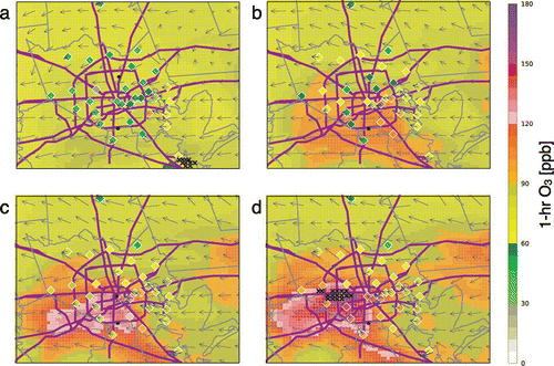
Figure 8. Spatial plot showing predictions from the base case simulation of 1-hr O3 concentrations at (a) 9:00 a.m., (b) 10:00 a.m., (c) 11:00 a.m., and (d) 12:00 p.m. on August 1, 2005. The diamond markers show measurement data from air quality monitors; if no data are available, the marker is a black dot. Color mismatches between the diamond markers (measurements) and grid cells (simulations) indicate model over- or underpredictions. Gray arrows show the simulated wind vectors at select grid cells. Arrows originating at the center of a diamond marker show measured wind data. Simulated NTOCs are marked with a black “X” (9:00 a.m. and 12:00 p.m. only). (Color figure available online).

Figure 9. (a) Observed and simulated (base case EI) 1-hr O3 concentrations at 12:00 p.m. on August 1, 2005. (b) Observed and simulated 1-hr O3 concentrations on August 1, 2005, recorded at the BAYP monitor. A 1-hr increase of 56 ppb was measured at 12:00 p.m.
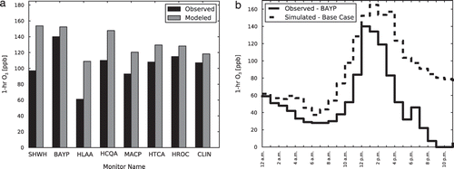
Figure 9. (a) Observed and simulated (base case EI) 1-hr O3 concentrations at 12:00 p.m. on August 1, 2005. (b) Observed and simulated 1-hr O3 concentrations on August 1, 2005, recorded at the BAYP monitor. A 1-hr increase of 56 ppb was measured at 12:00 p.m.

Figure 10. Observed and simulated (base case EI) 1-hr O3 concentrations on August 17, 2006. Observations were recorded at the DRPK monitor. Simulated values were extracted from a grid cell 5 km away from DRPK. A NTOC was measured and simulated at 11:00 a.m.
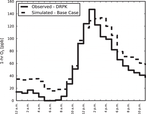
Figure 10. Observed and simulated (base case EI) 1-hr O3 concentrations on August 17, 2006. Observations were recorded at the DRPK monitor. Simulated values were extracted from a grid cell 5 km away from DRPK. A NTOC was measured and simulated at 11:00 a.m.

Figure 11. Plot (a) is a spatial plot showing simulated (base case EI) 1-hr O3 concentrations at 2:00 p.m. on August 17, 2006. The diamond markers show measurement data from air quality monitors. Color mismatches between the diamond markers (measurements) and grid cells (simulations) indicate model over- or underpredictions. Gray arrows show the simulated wind vectors at select grid cells. Arrows originating at the center of a diamond marker show measured wind data. Plot (b) shows observed and simulated (base case EI) 1-hr O3 concentrations for select monitors. (Color figure available online).
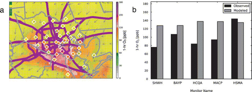
Figure 11. Plot (a) is a spatial plot showing simulated (base case EI) 1-hr O3 concentrations at 2:00 p.m. on August 17, 2006. The diamond markers show measurement data from air quality monitors. Color mismatches between the diamond markers (measurements) and grid cells (simulations) indicate model over- or underpredictions. Gray arrows show the simulated wind vectors at select grid cells. Arrows originating at the center of a diamond marker show measured wind data. Plot (b) shows observed and simulated (base case EI) 1-hr O3 concentrations for select monitors. (Color figure available online).

Reprints and Corporate Permissions

Please note: Selecting permissions does not provide access to the full text of the article, please see our help page How do I view content?

To request a reprint or corporate permissions for this article, please click on the relevant link below:

Academic Permissions

Please note: Selecting permissions does not provide access to the full text of the article, please see our help page How do I view content?

Obtain permissions instantly via Rightslink by clicking on the button below:

If you are unable to obtain permissions via Rightslink, please complete and submit this Permissions form. For more information, please visit our Permissions help page.