2,616
Views
17
CrossRef citations to date
0
Altmetric
Technical Papers

Pyrolysis and gasification-melting of automobile shredder residue

, , , , &
Pages 1137-1147 | Published online: 17 Sep 2013

Figures & data

Table 1. Analysis of ASR, cokes, and limestone

Figure 1. Schematic diagram of the fixed-bed pyrolyzer. 1, main bed; 2, ASR hopper; 3, screw feeder; 4, bed drain; 5, cyclone; 6, condenser; 7, gas sampling bottle; 8, I.D. fan.
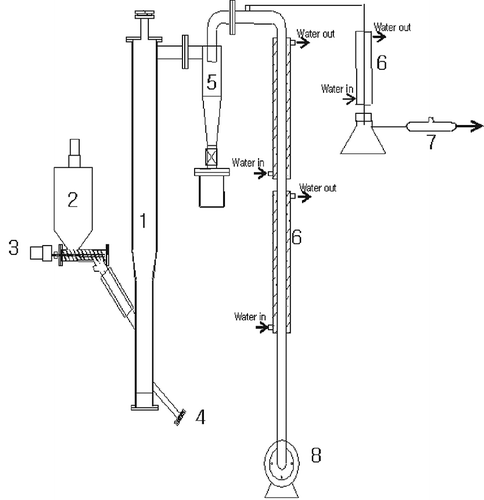
Figure 1. Schematic diagram of the fixed-bed pyrolyzer. 1, main bed; 2, ASR hopper; 3, screw feeder; 4, bed drain; 5, cyclone; 6, condenser; 7, gas sampling bottle; 8, I.D. fan.

Figure 2. The 5000 kg/day gasification-melting system for ASR.

Figure 2. The 5000 kg/day gasification-melting system for ASR.

Figure 3. Schematic diagram of the shaft furnace.

Figure 3. Schematic diagram of the shaft furnace.

Table 2. Operating conditions of the 5000 kg/day gasification-melting system

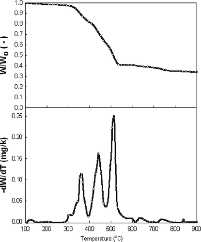
Figure 4. TGA and DTG curves of the ASR.

Figure 4. TGA and DTG curves of the ASR.

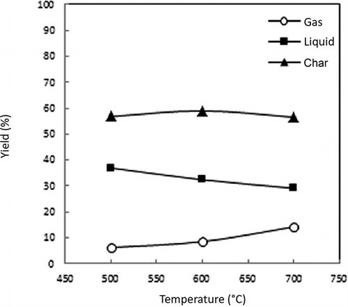
Figure 5. Effect of the ASR pyrolysis temperature on the product yield in the Lindberg furnace.

Figure 5. Effect of the ASR pyrolysis temperature on the product yield in the Lindberg furnace.

Table 3. Hydrocarbon compounds of product gas (Lindberg furnace)

Figure 6. Effect of the pyrolysis temperature on the product gas composition and calorific value in the Lindberg furnace (light fluff).
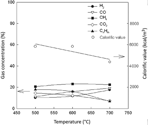
Figure 6. Effect of the pyrolysis temperature on the product gas composition and calorific value in the Lindberg furnace (light fluff).

Figure 7. Effect of the pyrolysis temperature on the product gas composition and calorific value in the Lindberg furnace (heavy fluff).
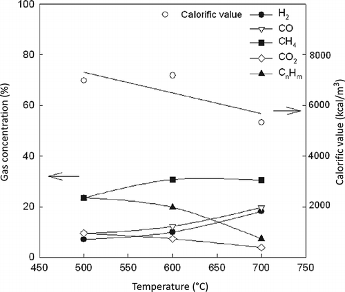
Figure 7. Effect of the pyrolysis temperature on the product gas composition and calorific value in the Lindberg furnace (heavy fluff).

Table 4. Hydrocarbon compounds of product gas (fixed-bed pyrolyzer)

Table 5. The heavy metal leachability of ASR and char

Figure 8. Effect of the pyrolysis temperature on the product gas composition and calorific value in the fixed-bed pyrolyzer.
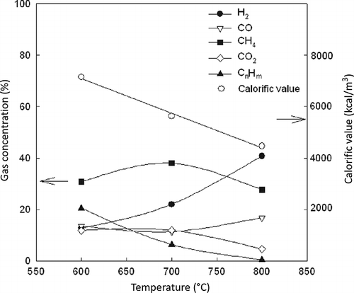
Figure 8. Effect of the pyrolysis temperature on the product gas composition and calorific value in the fixed-bed pyrolyzer.

Table 6. Operational data of the optimum conditions for the 5000 kg/day gasification-melting system

Figure 9. Slag generated from the gasification-melting system: (a) granulated slag; (b) metal grain.
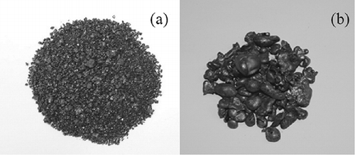
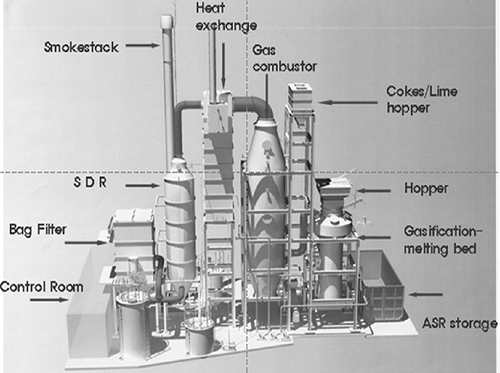
Figure 9. Slag generated from the gasification-melting system: (a) granulated slag; (b) metal grain.
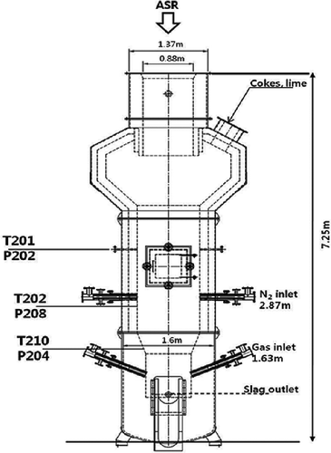
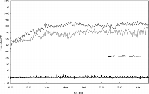
Figure 10. Temperature and pressure distribution of the gasification-melting system.

Figure 10. Temperature and pressure distribution of the gasification-melting system.

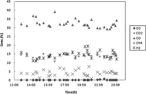
Figure 11. Concentration of the gas produced from the gasification-melting furnace.

Figure 11. Concentration of the gas produced from the gasification-melting furnace.

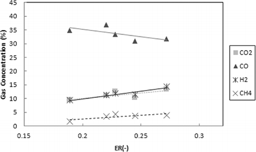
Figure 12. Gas compositions at various equivalence ratios (ERs).

Figure 12. Gas compositions at various equivalence ratios (ERs).

Table 7. Air pollution compound from stack (O2 12% reference)

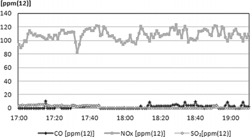
Figure 13. Air pollution compound (stack).

Figure 13. Air pollution compound (stack).

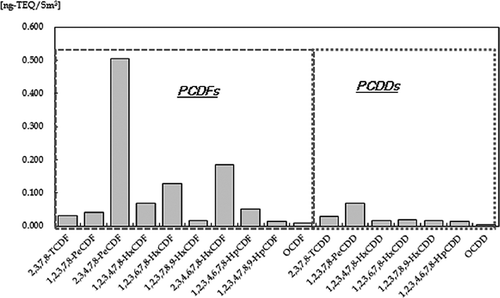
Figure 14. Dioxin from the stack.

Figure 14. Dioxin from the stack.

Table 8. The heavy metal leachability of the slag from pilot plant

Reprints and Corporate Permissions

Please note: Selecting permissions does not provide access to the full text of the article, please see our help page How do I view content?

To request a reprint or corporate permissions for this article, please click on the relevant link below:

Academic Permissions

Please note: Selecting permissions does not provide access to the full text of the article, please see our help page How do I view content?

Obtain permissions instantly via Rightslink by clicking on the button below:

If you are unable to obtain permissions via Rightslink, please complete and submit this Permissions form. For more information, please visit our Permissions help page.