Figures & data
Figure 1. The MMA and location of air quality monitoring stations (Obispado: Downtown [DT], La Pastora: Southeast [SE], Santa Catarina: Southwest [SW], San Nicolás: Northeast [NE], San Bernabé: Northwest [NW]).
![Figure 1. The MMA and location of air quality monitoring stations (Obispado: Downtown [DT], La Pastora: Southeast [SE], Santa Catarina: Southwest [SW], San Nicolás: Northeast [NE], San Bernabé: Northwest [NW]).](/cms/asset/f0e1c993-cb06-42da-8012-b67236d97b34/uawm_a_813875_o_f0001g.gif)
Figure 2. Nested modeling domains defined for the MM5 application (labeled as D01, DO2, and DO3).
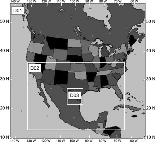
Figure 3. Emission reduction combinations of NOx and COVs (•) used in the control scenarios evaluated. The top right corner represents the base case.
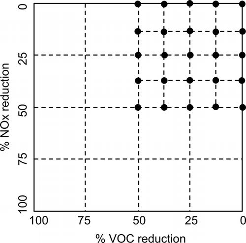
Figure 4. Ozone concentrations for August 26 at the time of modeled peak O3 concentration (19:00 UTC) at the MMA.
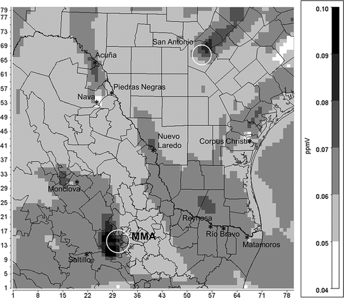
Figure 5. Ozone isopleths for August 26 at (a) NW, (b) NE, (c) DT, and (d) SE stations. The top right corner represents the base case.
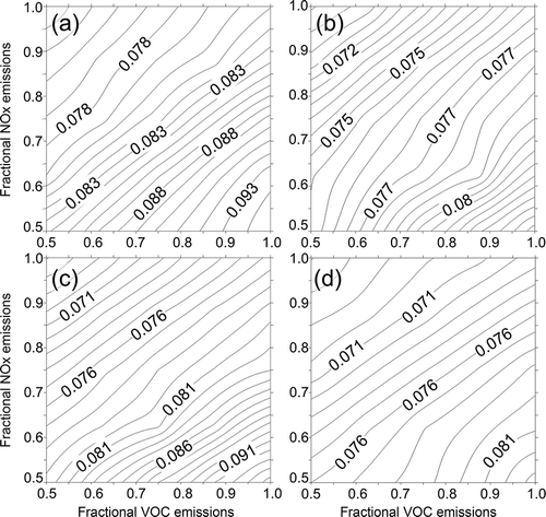
Table 1. Peak O3 concentrations (ppbv) for the basecase, VOC-only and NOx-only emission reduction scenarios
Figure 6. Ozone difference maps for VOC-only emission reduction scenarios: (a) 25% VOC reduction, (b) 50% VOC reduction.
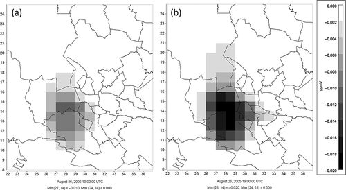
Figure 7. Ozone difference maps for NOx-only emission reduction scenarios: (a) 25% NOx reduction, (b) 50% NOx reduction (color figure available online).
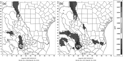
Figure 8. Model-derived VOC/NOx ratios for (a) the MMA and (b) the modeling domain.
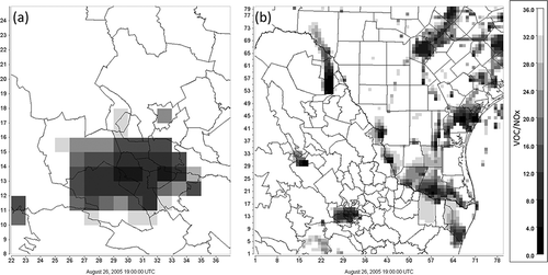
Table 2. Model-derived O3/NOy ratios at 19:00 UTC and the location of the air quality monitoring stations in the MMA
Figure 9. Model-derived O3-to-NOy ratios for the modeling domain.
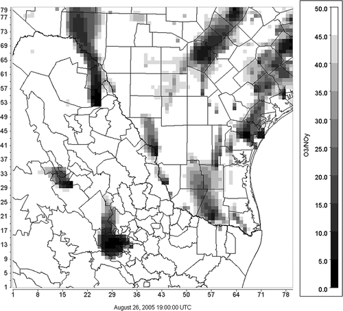
Figure 10. Model-derived O3-to-NOy ratios for (a) the MMA, (b) Monclova, and (c) Nava–Piedras Negras–Acuña for August 26, 2005, at 19:00 UTC (see text for details).
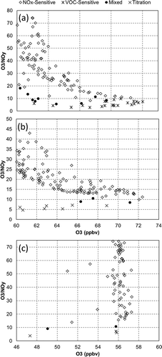
Figure S1. Main urban locations in Northeastern Mexico.
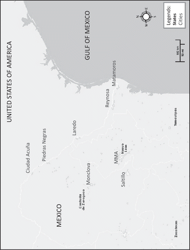
Figure S2. Classification tree used for episode selection.

Table S1. Statistical model performance evaluation for MM5 when applied to the D03 domain.
Table S2. O3 model performance evaluation for stations within the MMA(a).
Figure S3. Time series for simulated and observed O3 concentrations at the Obispado station (Julian day 236, 2005 = August 24, 2005).
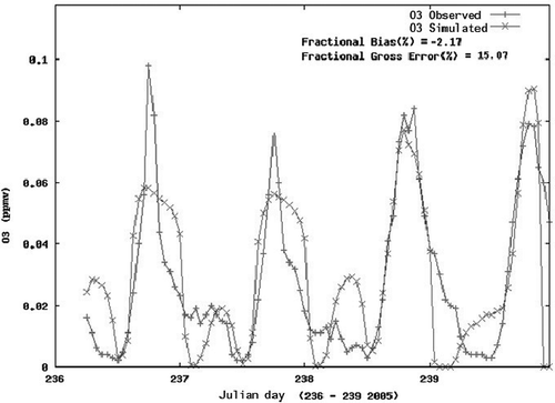
Figure S4. Simulated vs observed O3 scatterplot for the entire modeled episode (cutoff at 40 ppbv).
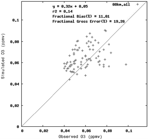
Figure S5. O3 concentration in and around the MMA for August 26, 2005. Diamonds represent the monitoring stations in the MMA.
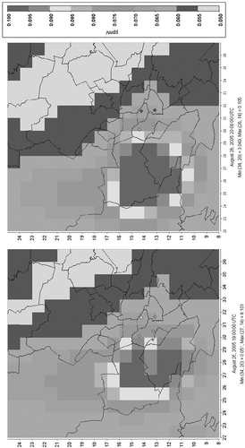
Figure S6. Ozone difference maps for combined VOC reductions with a 25% NOx reduction: a) 25% VOC reduction, b) 50% VOC reduction.
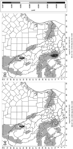
Figure S7. Ozone difference maps for combined VOC reductions with a 50% NOx reduction: a) 25% VOC reduction, b) 50% VOC reduction.
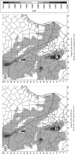
Figure S8. Domain-wide O3/NOz ratio.
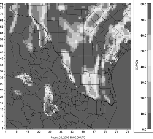
Figure S9. Domain-wide O3/HNO3 ratio.
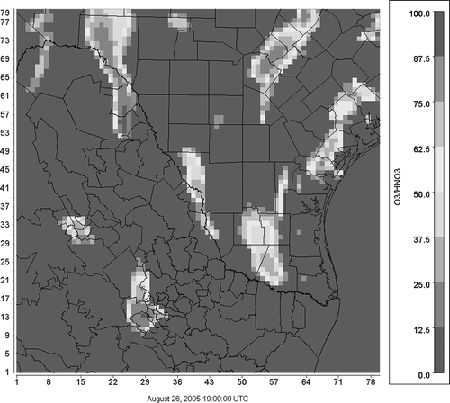
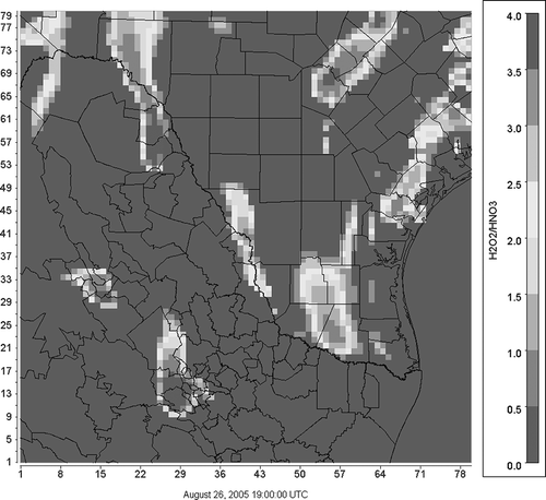
Figure S10. Domain-wide H2O2/HNO3 ratio.