Figures & data
Figure 1. Wet and dry size distributions at idle without an after treatment system, oil 1. The nano-SMPS measurements are shown with large markers and the long-SMPS measurements are shown with smaller markers. Thin vertical lines show the variation of the measured distributions (min-max).
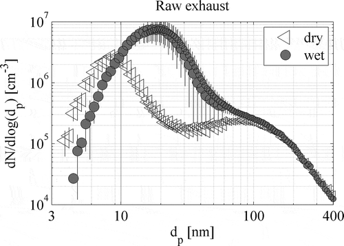
Figure 2. Left: Dry ion concentrations with (neutralized) and without (ion) neutralizer at idling load condition for two polarities (+, –), oil 1. The vertical lines show variation of the measured distributions. Dashed lines show the lognormal fits for the data. Dilution-corrected data. Right: Calculated charging probability values for the measured diameters (open symbols). The solid lines show the best Boltzmann equilibrium charging fits for the data (FBneg,FBpos). The fitted Boltzmann temperatures were 875 K and 745 K for negative and positive polarities, respectively. The dashed lines show average theoretical (Fuchs, Citation1963; Hoppel and Frick, Citation1986) charging probability values (fn) for the neutralizer, used in the calculation. The thin dashed lines represent variation caused by different ion parameters (Reischl et al., Citation1996).
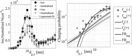
Figure 3. Dry distributions (nano-SMPS) for lubrication oils 1 and 2 at idle from raw exhaust. Long-SMPS distributions are presented in the inset to show the soot-mode distributions.
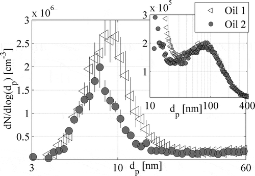
Table 1. Ion average lognormal-distribution parameters (geometric standard deviation GSD, geometric mean diameter GMD, ion concentration N) for both polarities with and without neutralizer (with uncertainties approximated from the data series maximums and minimums), and the calculated charging probabilities,
Figure 4. Right: Dry and wet particle size distributions with partial filter (A) and with partial filter and selective catalytic reduction catalytic converter (SCR) combination (B). Left: Average dry particle removal efficiencies for the aftertreatment systems E, and total particle number removal efficiencies for dry ET(dry) and wet ET(wet) particle emissions, oil 1.
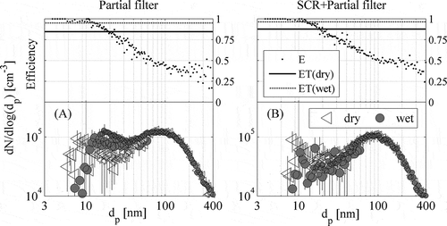
Figure 5. Dry size distributions with different fuel injection pressures (FIP) at idle and at 40 N-m torque, 800 rpm, oil 2. Dashed lines show the lognormal fits for the data sets. The applied FIP is given in the legends and torque and engine speed in the figure titles. Note the y-axis limits.
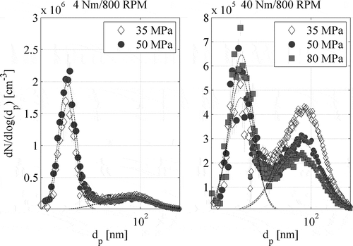
Table 2. Test oil specifications
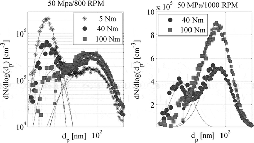
Figure 6. Dry particle size distributions with 50 MPa injection pressure at 800 rpm engine speed with three different torques (left) and at 1000 rpm engine speed with torques (right). Dynamometer torque is given in legends. The dashed black lines present the lognormal fits. Lubricant oil 2.