Figures & data
Figure 1. One-hour measurements of HCHO (indicated in red) during the BSEEC (Citation2010) study at a pipeline compressor station in the Barnett Shale in the afternoon of June 11, 2010. Note that the top of the figure points northward.
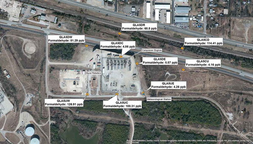
Table 1. Most important hazardous air pollutants (HAPs) emitted by the oil and gas industry and their effects screening level (ESL) values as determined by the state of Texas.
Table 2. Measurements of wind speed and direction in the afternoon of June 11, 2010, at the pipeline compressor station during the BSEEC (Citation2010) study.
Table 3. Model-inferred HCHO concentrations vs. measurements from BSEEC (Citation2010) study.
Figure 2. Airflow (blue streamlines) near the surface at the oil and gas site of in the afternoon of June 11, 2010, as simulated by the QUIC urban wind model assuming a southerly background wind. Also shown are 1-hr average ambient concentrations of HCHO (indicated in red) simulated by the HARC air quality model based on assimilated measurements from the BSEEC (Citation2010) study.
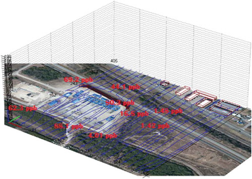
Figure 3. (Left) Mobile Acquisition of Real-Time Concentrations (MARC) vehicle. (Right) Position of anemometer and sample inlet mounted on top of MARC.
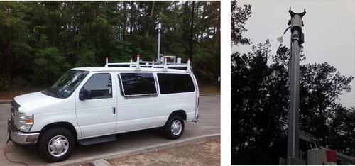
Figure 4. Example of plume tracking with MARC as it passes periodically through the plume of a large flare. The gaps are associated with periods where numerous barscans were performed to aid in identifying other potential hazardous pollutant emissions.
Figure 5. Barscan of an emission plume related to oil and gas production operations.
Figure 6. Diagram of dehumidifier system.
Figure 7. Hypothetical Web browser screenshot of the MARC real-time data broadcasting system. The actual site of the experiment in the Eagle Ford Shale cannot be shown due to a nondisclosure agreement.
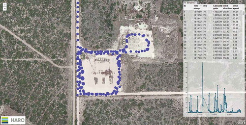
Figure 8. Mobile lab trajectory and corresponding benzene measurements at a natural gas production facility in the Eagle Ford Shale on the day a major flare was observed to be in operation.
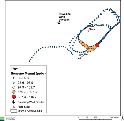
Figure 9. Isopleths of the surface concentration of benzene after 2 hr of flare emission inferred from MARC observations during the Eagle Ford study. Markers denote sensitive receptors.
Figure 10. Same as in Figure 8, but for the worst-case scenario.