1,479
Views
7
CrossRef citations to date
0
Altmetric
Technical Papers

Predicting emissions from oil and gas operations in the Uinta Basin, Utah

, , , , , & show all
Pages 528-545 | Received 04 Dec 2015, Accepted 08 Feb 2016, Published online: 11 Apr 2016

Figures & data

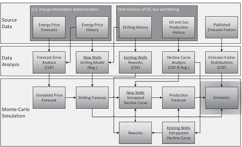
Figure 1. Diagram of the emission model.

Figure 1. Diagram of the emission model.

Figure 2. Boxplot of relative error between actual FPPs of (a) oil and (b) gas versus EIA AEO wellhead oil and gas prices in the Rocky Mountain region as calculated by eqs 1 and 2.
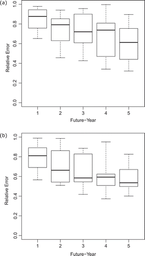
Figure 2. Boxplot of relative error between actual FPPs of (a) oil and (b) gas versus EIA AEO wellhead oil and gas prices in the Rocky Mountain region as calculated by eqs 1 and 2.

Table 1. Relative error beta distribution shape parameters α and β for oil and gas by future-year.

Table 2. Distributed lag drilling model fit (training period 1995–2009) and cross-validation (test period 2010–2014) results.

Figure 3. Training fit of distributed lag drilling models eqs 710. Actual drilling (Utah DOGM, Citation2015) and energy price (U.S. EIA, Citation2015c, Citation2015d) histories from January 1995 to December 2009 were used to find the best fit for each model using least-squares regression.
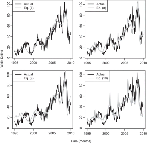
Figure 3. Training fit of distributed lag drilling models eqs 7–10. Actual drilling (Utah DOGM, Citation2015) and energy price (U.S. EIA, Citation2015c, Citation2015d) histories from January 1995 to December 2009 were used to find the best fit for each model using least-squares regression.

Figure 4. Cross-validation test of distributed lag drilling models eqs 710. Each model was tested against actual drilling (Utah DOGM, Citation2015) and energy price (U.S. EIA, Citation2015c, Citation2015d) histories from January 2010 to December 2014.
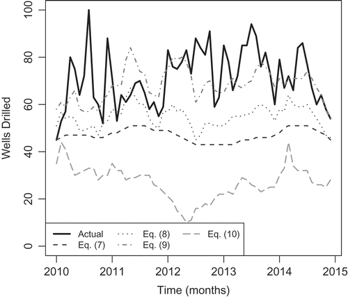
Figure 4. Cross-validation test of distributed lag drilling models eqs 7–10. Each model was tested against actual drilling (Utah DOGM, Citation2015) and energy price (U.S. EIA, Citation2015c, Citation2015d) histories from January 2010 to December 2014.

Figure 5. Well rework CDF describing probability of a well having at least one rework event based on (a) well age and (b) well type (oil or gas).
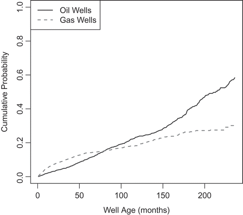
Figure 5. Well rework CDF describing probability of a well having at least one rework event based on (a) well age and (b) well type (oil or gas).

Figure 6. Decline curve analysis fitting (a) eq 11 to monthly oil rates and (b) eq 12 to cumulative oil production from an oil well in the Uinta Basin (API no. 43-013-31123). Dashed lines indicate the time index identified as a start/stop point by the algorithm responsible for finding distinct decline curve segments. Both the hyperbolic and cumulative curve fits use the same start/stop points. If only a single curve is found, then that curve counts as both the “first” and “last” curve. The production segment at the very beginning (t < 24 months) is ignored by the algorithm because some wells have short and sporadic decline curves during their first few years of operation.
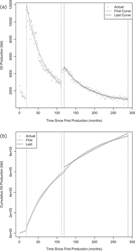
Figure 6. Decline curve analysis fitting (a) eq 11 to monthly oil rates and (b) eq 12 to cumulative oil production from an oil well in the Uinta Basin (API no. 43-013-31123). Dashed lines indicate the time index identified as a start/stop point by the algorithm responsible for finding distinct decline curve segments. Both the hyperbolic and cumulative curve fits use the same start/stop points. If only a single curve is found, then that curve counts as both the “first” and “last” curve. The production segment at the very beginning (t < 24 months) is ignored by the algorithm because some wells have short and sporadic decline curves during their first few years of operation.

Table 3. Best estimates of emission factors for the Uinta Basin prior to implementation of EPA’s New Source Performance Standards (NSPS) and new state rules on pneumatic controllers.

Table 4. Emission factors for oil production and transport from Picard (Citation2000).

Table 5. Change in emission factors for CO2e, CH4, and VOCs after the NSPS implementation for new wells (NETL 2014).a

Figure 7. Simulated energy price forecast for the cross-validation case for (a) oil and (b) gas FPPs. Various percentiles of results are shown as dotted lines, actual prices as solid black lines, and EIA AEO 2010 (U.S. EIA, Citation2010a) price forecasts as gray scale lines.
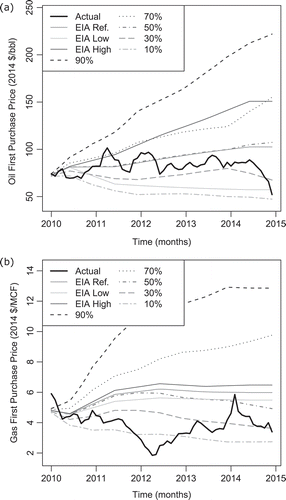
Figure 7. Simulated energy price forecast for the cross-validation case for (a) oil and (b) gas FPPs. Various percentiles of results are shown as dotted lines, actual prices as solid black lines, and EIA AEO 2010 (U.S. EIA, Citation2010a) price forecasts as gray scale lines.

Figure 8. Simulated energy price forecast for the prediction case for (a) oil and (b) gas FPPs. Various percentiles of results are shown as dotted lines, actual prices as solid black lines, and EIA AEO 2015 (U.S. EIA, 2015b) price forecasts as gray scale lines.
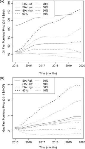
Figure 8. Simulated energy price forecast for the prediction case for (a) oil and (b) gas FPPs. Various percentiles of results are shown as dotted lines, actual prices as solid black lines, and EIA AEO 2015 (U.S. EIA, 2015b) price forecasts as gray scale lines.

Figure 9. Simulated energy price forecast for the prediction case for gas FPPs using the same random number generation seed as and , but with 105 MC simulation iterations instead of 104 iterations. Since the number of random draws changes, the directionality of the under/overprediction changes for the median case; however, the other percentile results are nearly identical between the two sample sizes.
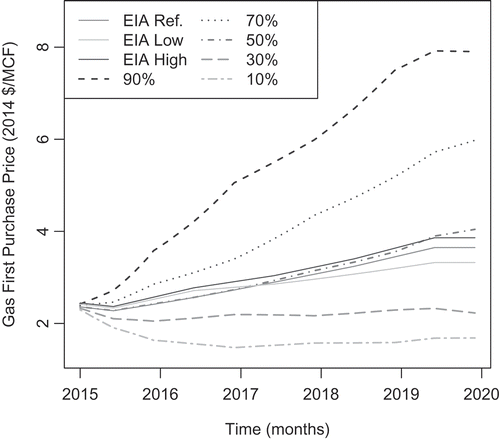
Figure 9. Simulated energy price forecast for the prediction case for gas FPPs using the same random number generation seed as Figures 7b and 8b, but with 105 MC simulation iterations instead of 104 iterations. Since the number of random draws changes, the directionality of the under/overprediction changes for the median case; however, the other percentile results are nearly identical between the two sample sizes.

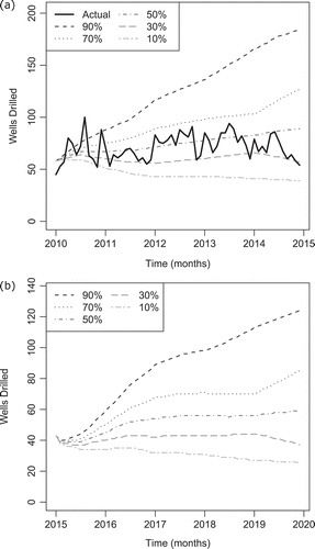
Figure 10. Drilling forecast for the (a) cross-validation and (b) prediction cases.

Figure 10. Drilling forecast for the (a) cross-validation and (b) prediction cases.

Figure 11. Production forecast for the cross-validation case for (a) oil production from new wells, (b) oil production from existing wells, (c) gas production from new wells, and (d) gas production from existing wells.
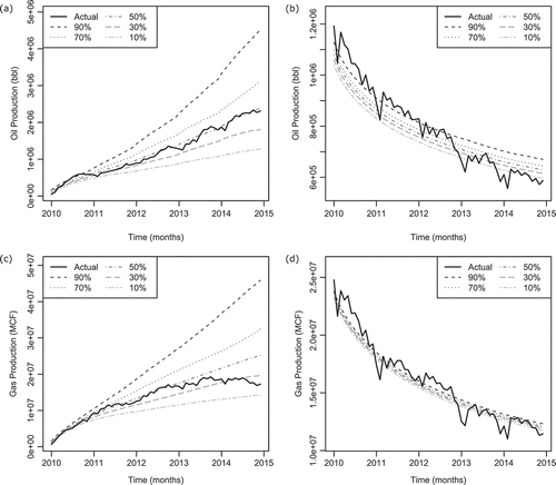
Figure 11. Production forecast for the cross-validation case for (a) oil production from new wells, (b) oil production from existing wells, (c) gas production from new wells, and (d) gas production from existing wells.

Figure 12. Production forecast for the cross-validation case for production of (a) oil and (b) gas from existing wells assuming no well reworks occur.
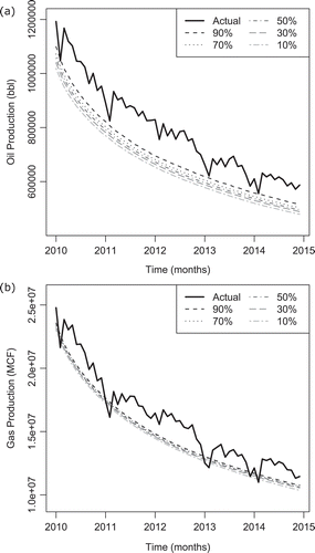
Figure 12. Production forecast for the cross-validation case for production of (a) oil and (b) gas from existing wells assuming no well reworks occur.

Figure 13. Production forecast for the cross-validation case for (a) oil and (b) gas production from new wells taking the actual drilling schedule as a given.
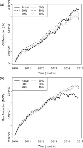
Figure 13. Production forecast for the cross-validation case for (a) oil and (b) gas production from new wells taking the actual drilling schedule as a given.

Figure 14. Production forecast for the prediction case for (a) oil and (b) gas production from all (new and existing) wells.
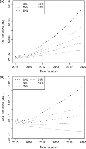
Figure 14. Production forecast for the prediction case for (a) oil and (b) gas production from all (new and existing) wells.

Figure 15. Fraction of total production that is generated from new wells as a function of time for the cross-validation case. Simulated results are shown as dotted lines and the actual production history as solid lines.
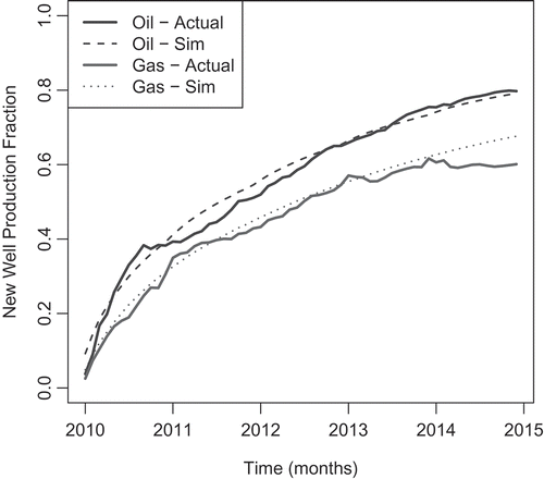
Figure 15. Fraction of total production that is generated from new wells as a function of time for the cross-validation case. Simulated results are shown as dotted lines and the actual production history as solid lines.

Figure 16. VOC emission percentile results for the (a) cross-validation and (b) prediction cases. Base emissions are shown as solid gray-scale lines, and reduced emissions from NSPS and state rules are shown as dotted lines.
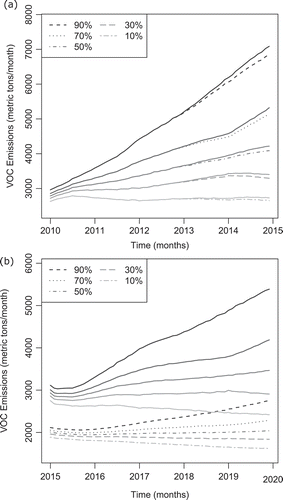
Figure 16. VOC emission percentile results for the (a) cross-validation and (b) prediction cases. Base emissions are shown as solid gray-scale lines, and reduced emissions from NSPS and state rules are shown as dotted lines.

Figure 17. Total median (50th percentile) VOC emissions for the (a) cross-validation and (b) prediction cases. Results are shown by year (Y1, Y2, etc.) and source for baseline emissions (B) and reduced emissions (R). Activities in the “Other” category include reworking, gas processing, oil production, and oil transportation.
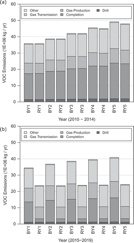
Figure 17. Total median (50th percentile) VOC emissions for the (a) cross-validation and (b) prediction cases. Results are shown by year (Y1, Y2, etc.) and source for baseline emissions (B) and reduced emissions (R). Activities in the “Other” category include reworking, gas processing, oil production, and oil transportation.
Supplemental material

Supplemental Material

Download PDF (464.6 KB)

Reprints and Corporate Permissions

Please note: Selecting permissions does not provide access to the full text of the article, please see our help page How do I view content?

To request a reprint or corporate permissions for this article, please click on the relevant link below:

Academic Permissions

Please note: Selecting permissions does not provide access to the full text of the article, please see our help page How do I view content?

Obtain permissions instantly via Rightslink by clicking on the button below:

If you are unable to obtain permissions via Rightslink, please complete and submit this Permissions form. For more information, please visit our Permissions help page.