Figures & data
Figure 1. Rigid discharge electrode.
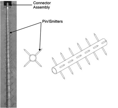
Figure 2. Experimental setup for testing electrodes in present study.
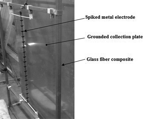
Figure 3. Discharge electrodes used in present study. The Hand lay-up HCE and Pre-preg HCE (right), the metal electrode (middle), and the Hand lay-up CE HCE (left).
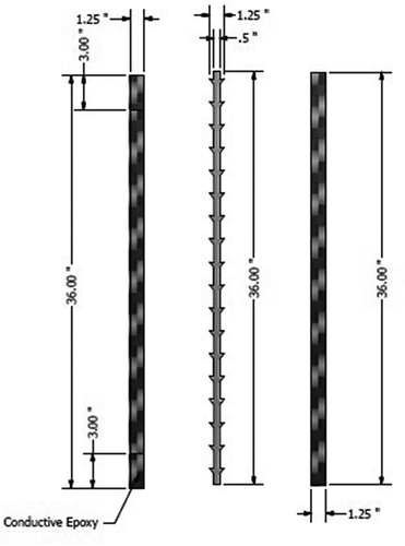
Table 1. Baseline samples.
Figure 4. V-I characteristic curves for the baseline materials.
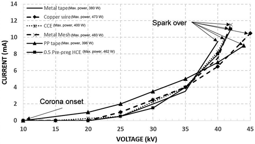
Figure 5. V-I characteristic curves for the PP HCE and the metal electrode.
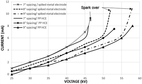
Figure 6. V-I characteristic curves for the Hand lay-up HCE and the metal electrode.

Figure 7. V-I characteristic curves for the Hand Lay-up CE HCE and the metal electrode.
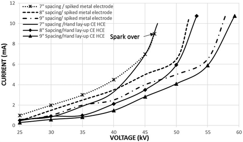
Figure 8. V-I characteristic curves for the Pre-preg HCE and the metal electrode.
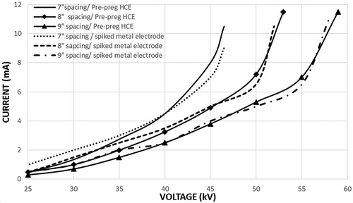
Figure 9. Peak power at variable distance (from the grounded plate).
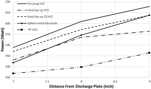
Table 2. Steady-state test.
Figure 10. Corona onset voltage.
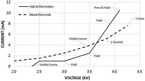
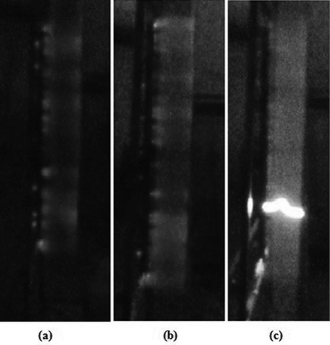
Figure 11. Three-point corona pattern for spiked metal. The left image was captured by using an UV camera.
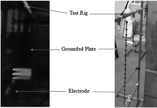
Figure 12. The uniform corona pattern for the HCE. (a) The corona at 54.3 kV and 8.5 mA. (b)The uniform corona. (c) The uniform corona at the spark over point.