1,003
Views
5
CrossRef citations to date
0
Altmetric
Technical Paper

Effect of diffusion limitation and substrate inhibition on steady states of a biofilm reactor treating a single pollutant

&
Pages 1107-1115 | Received 06 Jan 2019, Accepted 30 Apr 2019, Published online: 22 Aug 2019

Figures & data

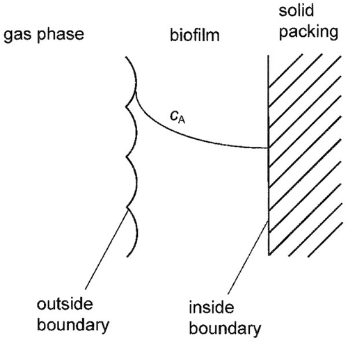
Figure 1. Schematics of a biofilm.

Figure 1. Schematics of a biofilm.

Table 1. Summary of used parameters.

Table 2. Model parameters for falsified kinetics (Li and De Visscher (Citation2008) and this study).

Figure 2. Concentration at the pollutant at the outside surface of the biofilm as a function of the inside surface concentration of the particle. Two stable steady states are predicted as indicated by the dashed lines (i.e., 13.7–15.4 g m−3). Parameters used in the calculations are shown in .
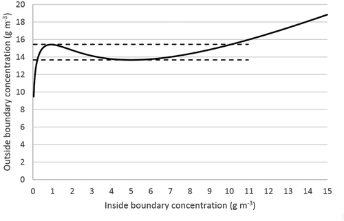
Figure 2. Concentration at the pollutant at the outside surface of the biofilm as a function of the inside surface concentration of the particle. Two stable steady states are predicted as indicated by the dashed lines (i.e., 13.7–15.4 g m−3). Parameters used in the calculations are shown in Table 2.

Figure 5. Diffusion profile in a biofilm as a function of biofilm depth showing two different steady states: dashed line – high active steady state; solid line – low activity steady state. Parameters used in the calculations are shown in . Outside boundary condition: 15 g m−3.
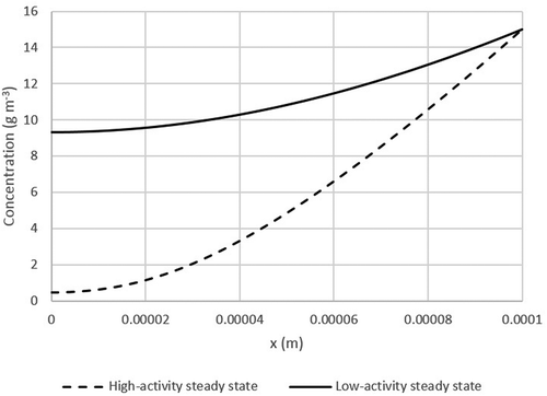
Figure 5. Diffusion profile in a biofilm as a function of biofilm depth showing two different steady states: dashed line – high active steady state; solid line – low activity steady state. Parameters used in the calculations are shown in Table 2. Outside boundary condition: 15 g m−3.

Figure 3. Parameter space where two steady states can occur (between the lines). Top left: π3 = 5; top right: π 3 = 2; bottom left: π3 = 1; bottom right: π3 = 0.5 Definitions of π variables: see eqs. (11, 12, 13).
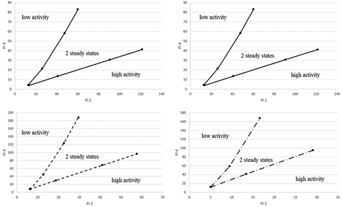
Figure 3. Parameter space where two steady states can occur (between the lines). Top left: π3 = 5; top right: π 3 = 2; bottom left: π3 = 1; bottom right: π3 = 0.5 Definitions of π variables: see eqs. (11, 12, 13).

Figure 4. Falsified kinetics – Simulation of various biofilms thicknesses with Haldane kinetics. Parameters used in the calculations are shown in .
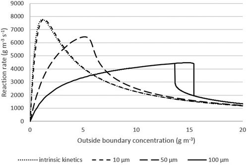
Figure 4. Falsified kinetics – Simulation of various biofilms thicknesses with Haldane kinetics. Parameters used in the calculations are shown in Table 2.

Reprints and Corporate Permissions

Please note: Selecting permissions does not provide access to the full text of the article, please see our help page How do I view content?

To request a reprint or corporate permissions for this article, please click on the relevant link below:

Academic Permissions

Please note: Selecting permissions does not provide access to the full text of the article, please see our help page How do I view content?

Obtain permissions instantly via Rightslink by clicking on the button below:

If you are unable to obtain permissions via Rightslink, please complete and submit this Permissions form. For more information, please visit our Permissions help page.