Figures & data
Figure 1. Schematic diagram of seven kinds of dust collecting plates.
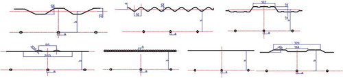
Table 1. Electrostatic precipitator parameters and operating parameters.
Figure 2. Computational mesh of the Rod-curtain type electrostatic precipitator.
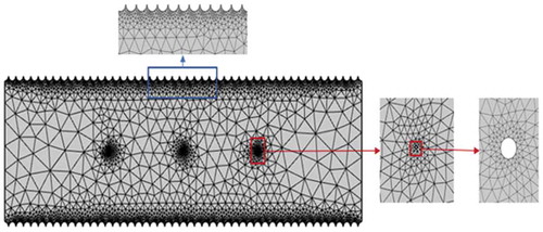
Table 2. Boundary conditions in electrostatic precipitator.
Figure 3. Implementation method and connection between physical modules.
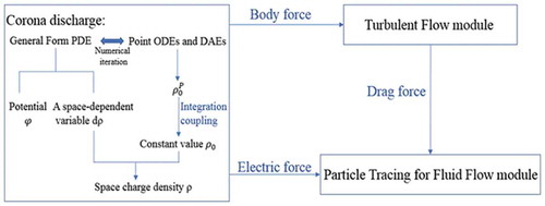
Figure 4. Comparison of potential computed with present model and experimental results by Penny & Matick.
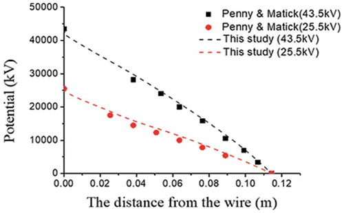
Figure 5. Comparison of flow streamlines computed in this paper.
Figure 6. Comparison of dust removal efficiency.
Figure 7. Magnitude of electric field strength (V / m) when using different shapes of collecting plates.
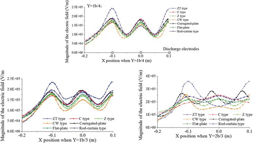
Figure 8. Effect of the shape of collecting plate on V–I characteristics.
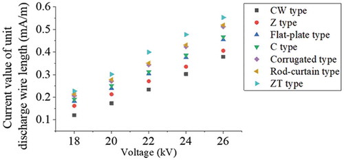
Figure 9. Charge density distribution curve of plate.
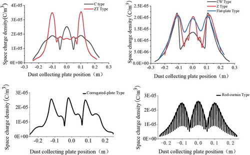
Figure 10. Space charge density(C/m3) distribution cloud map.
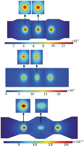
Figure 11. Comparison of space charge density on the surface of three discharge electrodes.
Figure 12. ESP streamline distribution (v = 0 m/s).
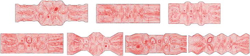
Figure 13. ESP streamline distribution (v = 1.0 m/s).
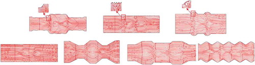
Figure 14. Relationship between the shape of collecting plates and the collection efficiency.