1,566
Views
10
CrossRef citations to date
0
Altmetric
Technical Paper

The application of leak detection and repair program in VOCs control in China’s petroleum refineries

, &
Pages 862-875 | Received 26 Oct 2019, Accepted 14 Apr 2020, Published online: 20 Jul 2020

Figures & data

Table 1. Basic information of four refineries.

Table 2. Equipment leak rate for petroleum equipment components.

Table 3. Numbers of equipment components in different refineries.

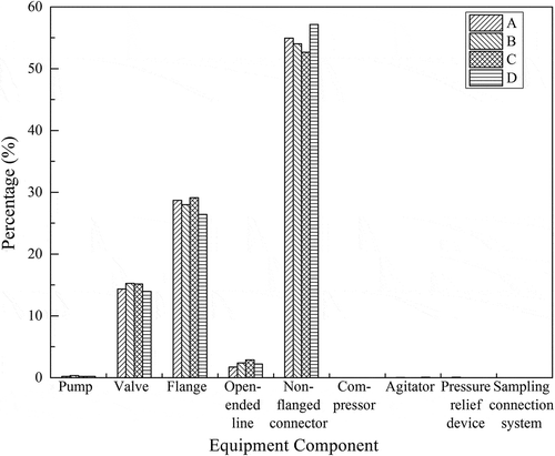
Figure 1. Distribution of equipment components in different refineries.

Figure 1. Distribution of equipment components in different refineries.

Table 4. Numbers of leaking components in different refineries.

Figure 2. Distribution of leaking components in different refineries.

Figure 2. Distribution of leaking components in different refineries.

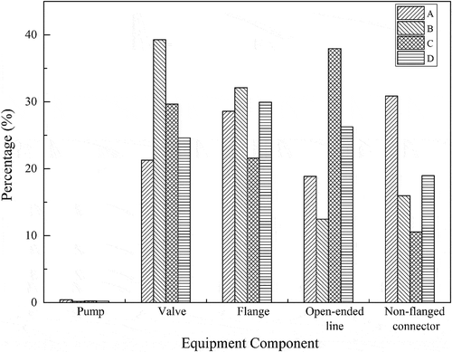
Figure 3. Distribution of high leaking components in total leaking components in different refineries.
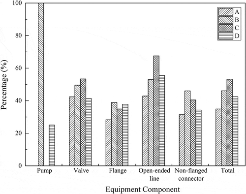
Figure 3. Distribution of high leaking components in total leaking components in different refineries.

Table 5. VOC emissions from all equipment components (unit: tons/year).

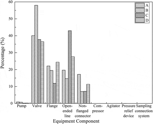
Figure 4. Distribution of VOC emissions from all equipment components.

Figure 4. Distribution of VOC emissions from all equipment components.

Table 6. VOC emissions from leaking components (unit: tons/year).

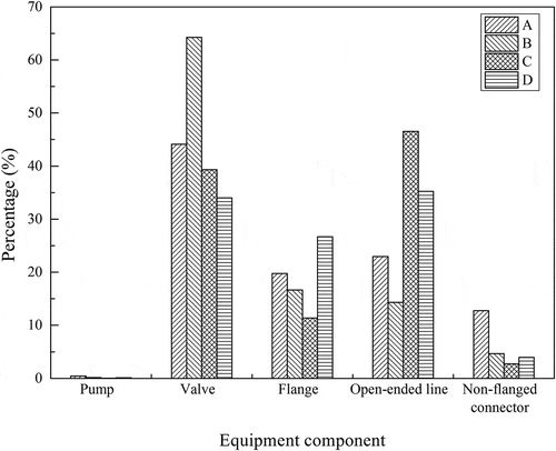
Figure 5. Distribution of VOC emissions from leaking components.

Figure 5. Distribution of VOC emissions from leaking components.

Table 7. Different proportion of VOC emissions.

Table 8. Common repair measures for leaking components.

Table 9. Numbers of DOR components in different refineries.

Table 10. Number of leaking components and VOC emissions after repair.

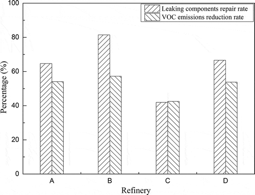
Figure 6. Leaking components repair rate and VOC emissions reduction rates after repair.

Figure 6. Leaking components repair rate and VOC emissions reduction rates after repair.

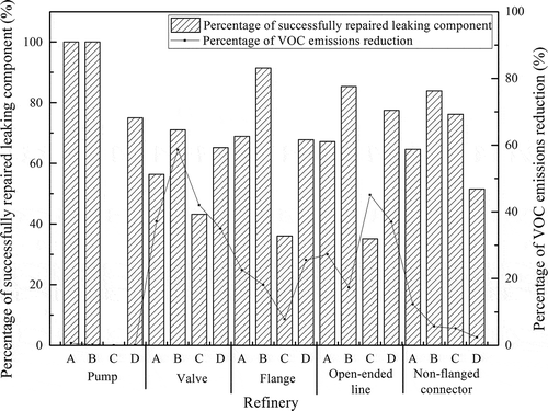
Figure 7. Repair results of different component categories.

Figure 7. Repair results of different component categories.

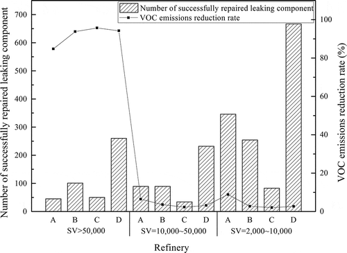
Figure 8. Repair results of different initial screening value ranges.

Figure 8. Repair results of different initial screening value ranges.

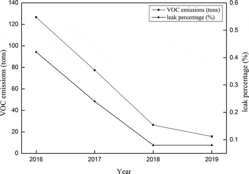
Figure 9. Results of LDAR implementation from 2016 to 2019.

Figure 9. Results of LDAR implementation from 2016 to 2019.

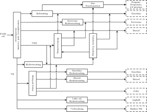
Figure 10. Typical process flow of a refinery.

Figure 10. Typical process flow of a refinery.

Table 11. Capacity of processing units (104 tons/year).

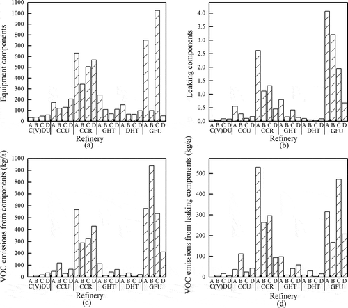
Figure 11. Number of components and VOC emissions in different processing units.

Figure 11. Number of components and VOC emissions in different processing units.

Table 12. Costs distribution of LDAR program for a medium refinery.

Supplemental material

Supplemental Material

Download MS Word (17.6 KB)

Reprints and Corporate Permissions

Please note: Selecting permissions does not provide access to the full text of the article, please see our help page How do I view content?

To request a reprint or corporate permissions for this article, please click on the relevant link below:

Academic Permissions

Please note: Selecting permissions does not provide access to the full text of the article, please see our help page How do I view content?

Obtain permissions instantly via Rightslink by clicking on the button below:

If you are unable to obtain permissions via Rightslink, please complete and submit this Permissions form. For more information, please visit our Permissions help page.