Figures & data
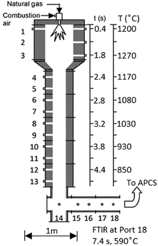
Figure 1. EPA’s pilot-scale “Rainbow” research furnace with temperature and calculated residence time profiles at 45 kW natural gas, 20% excess air used for model conditions. FTIR samples were collected at Port 18. Note the 1 m length scale. The Air Pollution Control System (APCS) consists of a facility afterburner, temperature quench, baghouse, and NaOH wet scrubber.

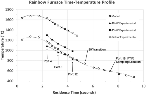
Figure 2. Temperature profile vs. calculated residence time for the Rainbow furnace at 20% excess air. Residence times correspond to the measured temperature profile used for the model (45 kW load) and the 64 kW experiment. These temperatures were obtained by suction pyrometer. Temperatures for the 40 and 45 kW experiments (solid symbols) are from bare thermocouple furnace centerline measurements taken immediately before PFAS injection at corresponding model port locations.

Table 1. Compounds measured by FTIR in the present study
Table 2. Comparison of measured (Exp) and calculated (Model) PFAS destruction efficiencies (DEs) within the Rainbow furnace as a function of compound and injection location. Measurements performed by FTIR at Port 18 (see )
Table 3. Comparison of measured (Exp) and calculated (Model) PFAS PICs (including residual PFAS and HF, in bold italic font) from the Rainbow furnace as a function of compound and injection location. Measurements performed by FTIR at Port 18 (see ). Measured species were >3x the SLC residuals and are shown to the nearest 10 ppbv with ± one standard deviation. Modeled species were >10 pptv, 45 kW furnace load
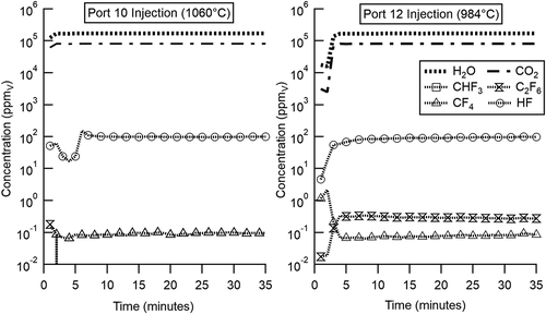
Figure 3. Real-time FTIR species concentrations measured at Port 18 depicting CHF3 injection at Ports 10 and 12 (45 kW load). In this case, CHF3 was introduced, and after a brief transitory period stable FTIR traces are achieved. Note the absence of detectable CHF3, CF4 formation as a PIC at both Port 10 and Port 12, and C2F6 formation as a PIC during Port 12 injection. CF4 concentrations (above) were <3x the CLS residual value and therefore, not reported in .

