424
Views
0
CrossRef citations to date
0
Altmetric
Technical Papers

Evaluation of a self-cleaning portable dust collector for reducing worker exposures to silica at hydraulic-fracturing sites

, , , &
Pages 109-119 | Received 04 Jan 2022, Accepted 17 Oct 2022, Published online: 16 Dec 2022

Figures & data

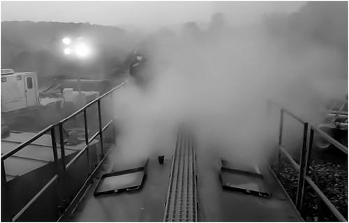
Figure 1. Dust escaping from thief hatches on a sand mover.

Figure 1. Dust escaping from thief hatches on a sand mover.

Figure 2. This dust-collection system utilizes four cartridge filters and a pulse-jet cleaning system.
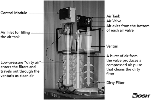
Figure 2. This dust-collection system utilizes four cartridge filters and a pulse-jet cleaning system.

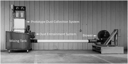
Figure 3. Lab testbed with self-cleaning dust-collection system mounted on top of the mixing tank.

Figure 3. Lab testbed with self-cleaning dust-collection system mounted on top of the mixing tank.

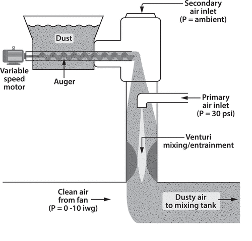
Figure 4. Dust generator setup.

Figure 4. Dust generator setup.

Figure 5. Calculated relationship between air volume (in scf) and pulse duration (ms), assuming critical flow through the nozzle.
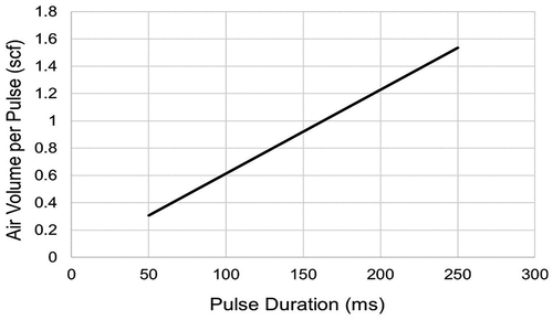
Figure 5. Calculated relationship between air volume (in scf) and pulse duration (ms), assuming critical flow through the nozzle.

Figure 6. Relationship between air volume in tank (in scf) and pressure in tank (psi), calculated using Eq. 2.
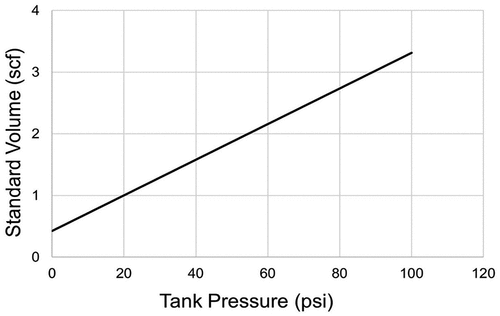
Figure 6. Relationship between air volume in tank (in scf) and pressure in tank (psi), calculated using Eq. 2.

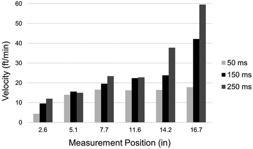
Figure 7. Pulse profiles from top to bottom along the length of the filter using 60 psi tank pressure and an 8-inch standoff.

Figure 7. Pulse profiles from top to bottom along the length of the filter using 60 psi tank pressure and an 8-inch standoff.

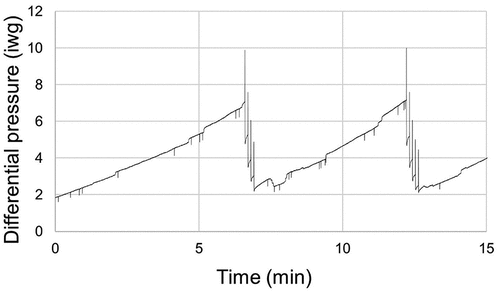
Figure 8. Graph of differential pressure data from a test at a flow rate of 1300 cfm.

Figure 8. Graph of differential pressure data from a test at a flow rate of 1300 cfm.

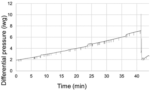
Figure 9. Graph of differential pressure data from a test at a flow rate of 600 cfm.

Figure 9. Graph of differential pressure data from a test at a flow rate of 600 cfm.

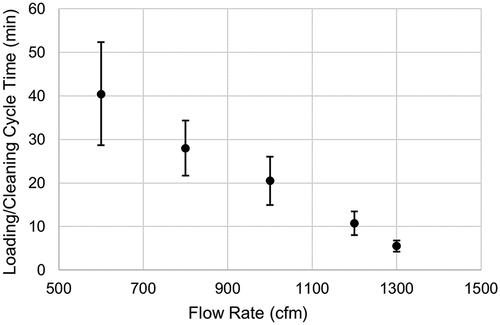
Figure 10. Graph of loading/cleaning cycle time vs flow rate.

Figure 10. Graph of loading/cleaning cycle time vs flow rate.

Data availability statement

The data that support the findings of this study are available from the corresponding author, GWK, upon reasonable request.

Reprints and Corporate Permissions

Please note: Selecting permissions does not provide access to the full text of the article, please see our help page How do I view content?

To request a reprint or corporate permissions for this article, please click on the relevant link below:

Academic Permissions

Please note: Selecting permissions does not provide access to the full text of the article, please see our help page How do I view content?

Obtain permissions instantly via Rightslink by clicking on the button below:

If you are unable to obtain permissions via Rightslink, please complete and submit this Permissions form. For more information, please visit our Permissions help page.