Figures & data
Figure 1. (a) Process for handling low- and intermediate-level radioactive waste from the generating facility to the disposal site. (b) a schematic of the proposed radioactive waste tracking system.
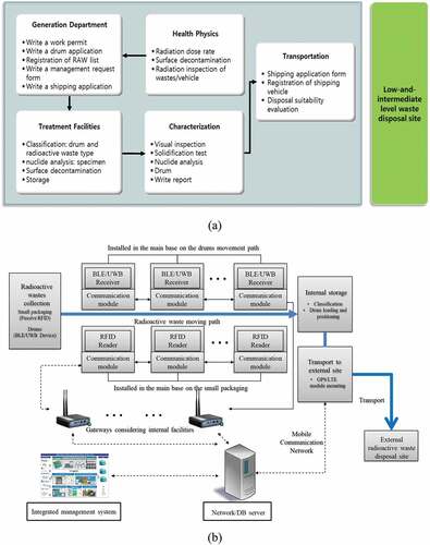
Figure 2. (a) NFC test configuration for drum positioning performance. Performance test on (b) a regular wooden table and (c) metal drum.
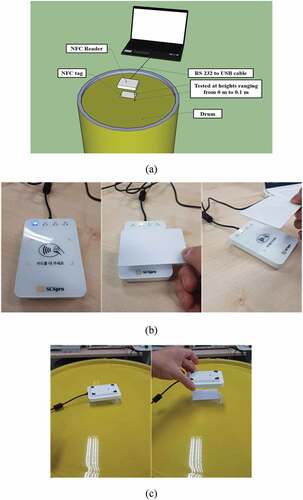
Figure 3. Diagram of the IR module transmission and reception test configuration.
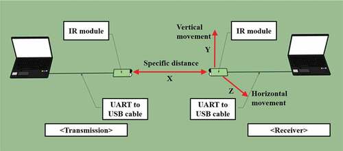
Figure 4. (a) Design and components of the pallet and (b) the pallet module layout.
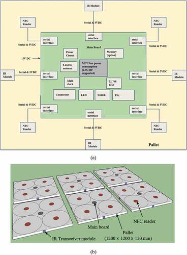
Table 1. Models and manufacturers of the modules used on a pallet.
Figure 5. (a) Position of the attached magnetic sensor on a drum and (b) configuration of the magnetic sensors.
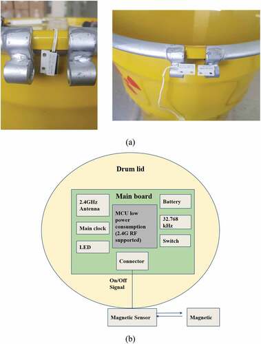
Figure 6. Example of the built-in application of an NFC reader in a pallet.
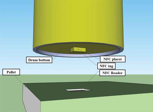
Table 2. Operational vertical distance range according to the distance between NFC tag and drum surface.
Table 3. Results of the IR transmit/receive test.
Table 4. Test results according to the materials interfering with electromagnetic signals between the transmitting and receiving modules.
Table 5. Results from analysis of the sensor characteristics according to the position of the magnetic sensor.
Table 6. Estimated power consumption of a drum node.
Table 7. Estimated power consumption of a pallet node.
Figure 7. Confirmation of the remote tests of the lid closed/open status using the magnetic sensor of (a) one drum and (b) three drums.
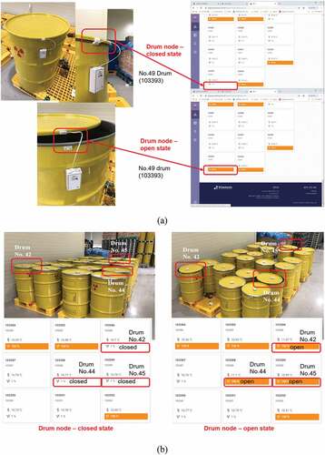
Figure 8. Test configuration for the test of drum indoor tracking.
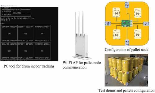
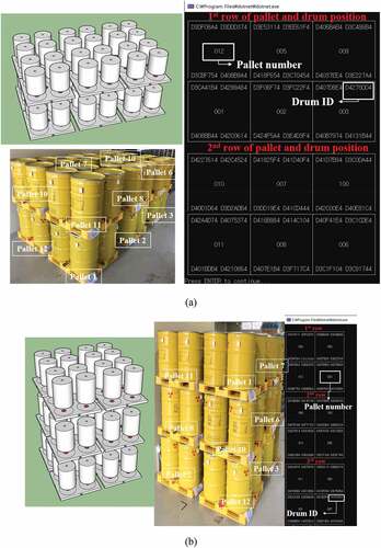
Figure 9. Pallet arrays with (a) 2 × 3 × 2 and (b) 2 × 2 × 3 configurations and their indoor tracking results.