
Figures & data
Figure 1. Experimental system diagram for formaldehyde purification performance testing 1. Formaldehyde generator; 2. Three-way valve; 3. Solar simulator; 4. Experimental cabin; 5. Stirring fan; 6. Catalyst carrier; 7. Catalyst; 8. Glass wall surface; 9. Formaldehyde detector; 10. Temperature sensor; 11. Vacuum pump; 12. Detection.
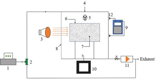
Figure 2. ULTRA-VITALUX spectral radiant power distribution.
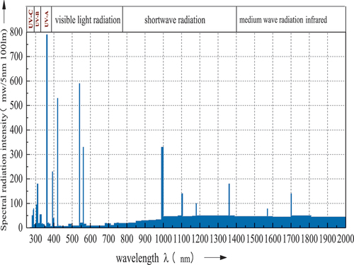
Figure 3. Absorption characteristics of MnOx-CeO2 catalyst.
Figure 4. H2-TPR spectrum of MnOx-CeO2 catalyst.
Figure 5. Scanning electron micrographs of the MnOx-CeO2 catalyst at 20,000 and 50,000
magnification.
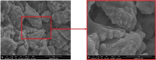
Figure 6. N2 adsorption and desorption isotherm curve of MnOx-CeO2 catalyst.
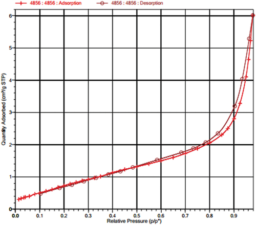
Table 1. Specific surface area, pore volume, and average pore diameter of the MnOx-CeO2 catalyst.
Table 2. Experimental condition table.
Figure 7. Reaction rate of MnOx-CeO2-catalyzed formaldehyde at different temperatures, concentrations and loadings.
Figure 8. MVK model fitting of formaldehyde catalysis at different temperatures.
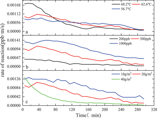
Figure 9. MVK model fitting of formaldehyde catalysis at different concentrations.
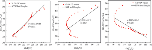
Figure 10. LH model fitting of formaldehyde catalysis at different temperatures.
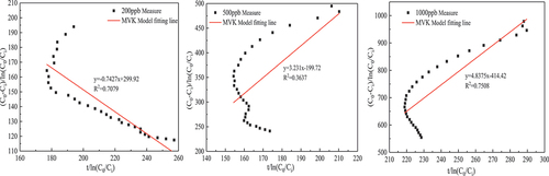
Figure 11. LH model fitting of formaldehyde catalysis at different concentrations.
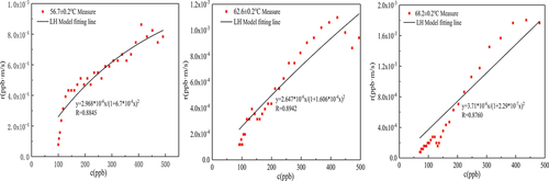
Figure 12. ER model fitting of formaldehyde catalysis at different temperatures.
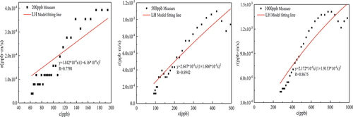
Figure 13. ER model fitting of formaldehyde catalysis at different concentrations.
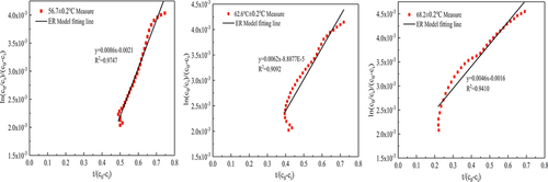
Figure 14. ER model fitting of formaldehyde catalysis at different concentrations.
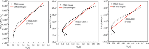
Table 3. MVK kinetic model parameters of thermal catalytic oxidation of formaldehyde.
Table 4. LH kinetic model parameters of thermal catalytic oxidation of formaldehyde.
Table 5. ER kinetic model parameters of thermal catalytic oxidation of formaldehyde.
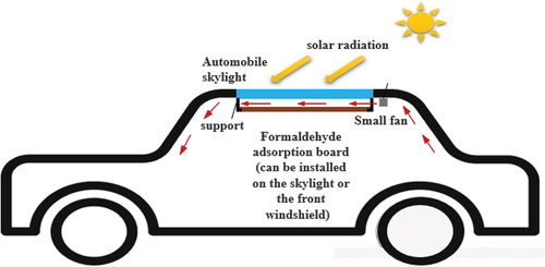
Figure 15. Diagram of the formaldehyde purification system in the car.
Data availability statement
The authors confirm that the data supporting the findings of this study are available within the article.