870
Views
4
CrossRef citations to date
0
Altmetric
Original Articles

Morphology of adaptation and morphogenesis in stomatopod eyes

, &
Pages 123-134 | Received 12 Jan 2006, Accepted 30 Mar 2006, Published online: 05 Jun 2007

Figures & data

Figure 1. Eyes ofLysiosquillina maculata (at left and centre) and L. sulcata (right). At left a triple pseudopupil; centre and right: total internal (dark regions of the eye) and external (bright regions) reflection. All eyes are 10±1 mm.
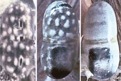
Figure 1. Eyes ofLysiosquillina maculata (at left and centre) and L. sulcata (right). At left a triple pseudopupil; centre and right: total internal (dark regions of the eye) and external (bright regions) reflection. All eyes are 10±1 mm.

Figure 2. a, Patterns of summed Gaussian response curves constituting the outputs from the ommatidia from the retina when a point light source passes in front of a column of ommatidia (from tip to tip across the midband) in the eye of Squilla mantis at a speed of 10 cm/s. At the left: in a small eye the point passes at a distance of 1 cm, right: the point passes at a distance of 3 cm in front of a large eye. Ordinates: number of ommatidia with overlapping visual fields (i.e. Gaussian sensitivity curves), i.e. ommatidia which would be stimulated simultaneously. Abscissae: time in milliseconds. For small and large eyes similar patterns of overlap result for shorter, respectively, longer distances, which are correlated to the shorter or longer raptorial appendages. b–e, Patterns of stimulated activity in the lamina ganglionaris of: b, c, Squilla mantis (living in dim light); d, e, Gonodactylus oerstedi (from bright light) when a rectangle passes in front of the eye. Ordinate: mV = potentials generated in the lamina, abscissae: columns and rows of ommatidia stimulated by the rectangle. b, target 2×0.5 cm moves at a speed of 10 cm/s at a distance of 1 cm from the eye, ordinate from O to 12 mV; c, a 2×0.5 cm rectangle moves at a distance of 2 cm at a speed of 5 cm/s, Ordinate: 0–120 mV. d, Target size 2×0.5 cm, speed 10 cm/s, distance from eye 1 cm, ordinate: 0–70 mV; e, Target 2×0.5 cm, speed 5 cm/s, distance 2 cm, ordinate 0–50 mV. f, Calculated acceptance angles, apertures and visual fields at indicated distances for different stomatopods: E = Echinosquilla guerini, Sm = Squilla mantis, Se = Squilla empusa, H = Hemisquilla ensigera, O = Odontodactylus scyllarus, G = Gonodactylus spp., Pv, Pd = Pseudosquilla ciliata, Pv posterior, Pd anterior ommatidia. Numbers from top to bottom: sizes of visual fields at indicated distances at approximate striking distances of species, degrees of acceptance angles, degrees of aperture angles, diameters of distal rhabdoms.
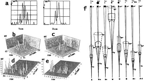
Figure 2. a, Patterns of summed Gaussian response curves constituting the outputs from the ommatidia from the retina when a point light source passes in front of a column of ommatidia (from tip to tip across the midband) in the eye of Squilla mantis at a speed of 10 cm/s. At the left: in a small eye the point passes at a distance of 1 cm, right: the point passes at a distance of 3 cm in front of a large eye. Ordinates: number of ommatidia with overlapping visual fields (i.e. Gaussian sensitivity curves), i.e. ommatidia which would be stimulated simultaneously. Abscissae: time in milliseconds. For small and large eyes similar patterns of overlap result for shorter, respectively, longer distances, which are correlated to the shorter or longer raptorial appendages. b–e, Patterns of stimulated activity in the lamina ganglionaris of: b, c, Squilla mantis (living in dim light); d, e, Gonodactylus oerstedi (from bright light) when a rectangle passes in front of the eye. Ordinate: mV = potentials generated in the lamina, abscissae: columns and rows of ommatidia stimulated by the rectangle. b, target 2×0.5 cm moves at a speed of 10 cm/s at a distance of 1 cm from the eye, ordinate from O to 12 mV; c, a 2×0.5 cm rectangle moves at a distance of 2 cm at a speed of 5 cm/s, Ordinate: 0–120 mV. d, Target size 2×0.5 cm, speed 10 cm/s, distance from eye 1 cm, ordinate: 0–70 mV; e, Target 2×0.5 cm, speed 5 cm/s, distance 2 cm, ordinate 0–50 mV. f, Calculated acceptance angles, apertures and visual fields at indicated distances for different stomatopods: E = Echinosquilla guerini, Sm = Squilla mantis, Se = Squilla empusa, H = Hemisquilla ensigera, O = Odontodactylus scyllarus, G = Gonodactylus spp., Pv, Pd = Pseudosquilla ciliata, Pv posterior, Pd anterior ommatidia. Numbers from top to bottom: sizes of visual fields at indicated distances at approximate striking distances of species, degrees of acceptance angles, degrees of aperture angles, diameters of distal rhabdoms.

Figure 3. a, The eye of Lysiosquillina maculata showing the varying sizes of ommatidia along a column across the midband. Bar: 1 mm. b, The rhabdom of S. mantis and c, that of L. maculata at same amplification. Bars: 50 µm.
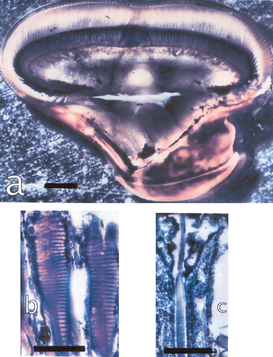
Figure 3. a, The eye of Lysiosquillina maculata showing the varying sizes of ommatidia along a column across the midband. Bar: 1 mm. b, The rhabdom of S. mantis and c, that of L. maculata at same amplification. Bars: 50 µm.

Table I. Mean values of sizes of ommatidial components from the eyes of two L. maculata, one adapted to light (LA), the other adapted to the dark (DA).

Figure 4. a, Section through a corneal facet of Odontodactylus scyllarus, bar: 11.4 µm; b, Pseudosquilla ciliata, bar: 30.8 µm; c, Meiosquilla oculinova, corneal surface seen from laterally, bar 60 µm ; d, S. mantis (diameter of facet is about 100 µm). Note the external surface facet with different refractive indices in a.
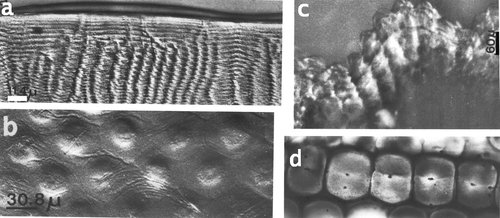
Figure 4. a, Section through a corneal facet of Odontodactylus scyllarus, bar: 11.4 µm; b, Pseudosquilla ciliata, bar: 30.8 µm; c, Meiosquilla oculinova, corneal surface seen from laterally, bar 60 µm ; d, S. mantis (diameter of facet is about 100 µm). Note the external surface facet with different refractive indices in a.

Figure 5. a, A section through a cone in the eye of a large L. maculata with the four enforcements, bar: 25 µm. b, A piece of the cone enveloping network membrane in a tangential section of a cone, bar: 25 µm. c, Section through cones from a small L. m. with the four enforcements in each cone, bar: 10 µm. d, Section through cones, from cornea (left) towards the retina. Proximal cones are multiply folded. Cones are surrounded by the myofibril containing ‘veils’, bar: 100 µm. e, Section through cones and the surrounding veils containing six groups of myofibrils (arrow) around each cone, bar: 100 µm. f, Section parallel to the optical axis through a cone and the veils attached to the cornea. Star: one of the four inserted enforcements. Bar: 50 µm. g, Same as f but a section near the optical axis. Stars: two inserted enforcements. Bar: 50 µm. h–i, Cones and veils in longitudinal sections showing also the network of the cone enveloping membrane (triangles). Arrows indicate the myofibrils. Bars: 50 µm.
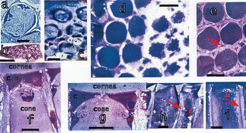
Figure 5. a, A section through a cone in the eye of a large L. maculata with the four enforcements, bar: 25 µm. b, A piece of the cone enveloping network membrane in a tangential section of a cone, bar: 25 µm. c, Section through cones from a small L. m. with the four enforcements in each cone, bar: 10 µm. d, Section through cones, from cornea (left) towards the retina. Proximal cones are multiply folded. Cones are surrounded by the myofibril containing ‘veils’, bar: 100 µm. e, Section through cones and the surrounding veils containing six groups of myofibrils (arrow) around each cone, bar: 100 µm. f, Section parallel to the optical axis through a cone and the veils attached to the cornea. Star: one of the four inserted enforcements. Bar: 50 µm. g, Same as f but a section near the optical axis. Stars: two inserted enforcements. Bar: 50 µm. h–i, Cones and veils in longitudinal sections showing also the network of the cone enveloping membrane (triangles). Arrows indicate the myofibrils. Bars: 50 µm.

Figure 6. a, Schematic drawing of dark‐adapted and light‐adapted ommatidia showing also the components of the ommatidia. b, Tangential section at the distal side of the basement membrane, black: the feet of the accessory pigment cells attached to the basement membrane, blue: the proximal retinular cells passing through the basement membrane. Bar: 50 µm. c, Drawing of the proximal rhabdom tips (blue, rh), retinular cells (yellow) and feet of accessory pigment (black) cells. Outlined in red an accessory pigment cell and the rhabdom tips of the three ommatidia connected by this accessory pigment cell. d, The distal retina surface with the rhabdoms, the four lobes of the eighth retinular cell and the four cone extensions on the rhabdom corners (arrowhead). On the left drawing of the section showing the cone extensions on the rhabdom corners and the four lobes of the eighth retinular cells. Seven normal retinular cells and six accessory pigment cells surround each rhabdom. Bar: 20 µm. e, Longitudinal section of the distal retina showing two of the four lobes of the eighth retinular cell, the rhabdom and distal tips of the retinular cells. Bar: 20 µm. The drawing shows the correlation between the lobes of the eighth cell and the rhabdom. f, Section through a dark‐adapted and g, a light‐adapted retina. Perirhabdomal spaces (arrows) are slightly wider in dark‐adapted eyes and black pigment accumulated around the distal rhabdom. Bar in f: 30 µm, in g 20 µm.
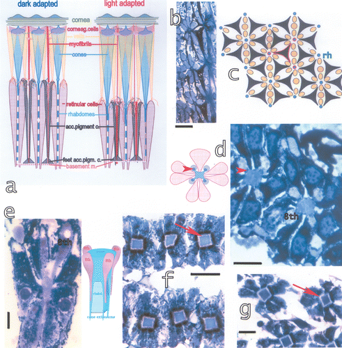
Figure 6. a, Schematic drawing of dark‐adapted and light‐adapted ommatidia showing also the components of the ommatidia. b, Tangential section at the distal side of the basement membrane, black: the feet of the accessory pigment cells attached to the basement membrane, blue: the proximal retinular cells passing through the basement membrane. Bar: 50 µm. c, Drawing of the proximal rhabdom tips (blue, rh), retinular cells (yellow) and feet of accessory pigment (black) cells. Outlined in red an accessory pigment cell and the rhabdom tips of the three ommatidia connected by this accessory pigment cell. d, The distal retina surface with the rhabdoms, the four lobes of the eighth retinular cell and the four cone extensions on the rhabdom corners (arrowhead). On the left drawing of the section showing the cone extensions on the rhabdom corners and the four lobes of the eighth retinular cells. Seven normal retinular cells and six accessory pigment cells surround each rhabdom. Bar: 20 µm. e, Longitudinal section of the distal retina showing two of the four lobes of the eighth retinular cell, the rhabdom and distal tips of the retinular cells. Bar: 20 µm. The drawing shows the correlation between the lobes of the eighth cell and the rhabdom. f, Section through a dark‐adapted and g, a light‐adapted retina. Perirhabdomal spaces (arrows) are slightly wider in dark‐adapted eyes and black pigment accumulated around the distal rhabdom. Bar in f: 30 µm, in g 20 µm.

Figure 7. a, Section of a dark‐adapted retina of L. m. seen in epifluorescent light (λe = 305 nm) showing the bent connections (arrow) from the cones to the rhabdoms. Bar: 20 µm. b, In the light‐adapted eyes the crystalline cones suddenly restrict to slim proximal parts which enter the retina and contact the rhabdoms. c, In light‐adapted eyes a thin facet (arrow) underlies the corneal facet and may contribute to the reflection. Bar: 20 µm. d, Section through a juvenile eye of L. m. showing the bending of cones in these quickly growing eyes. Bar: 300 µm. e–f, Connecting structures (arrows) between the cornea and the crystalline cones in a growing eye of S. mantis. These structures possibly form later on the enforcements around the distal tips of the cones. Bar in e 100 µm, in f 50 µm.
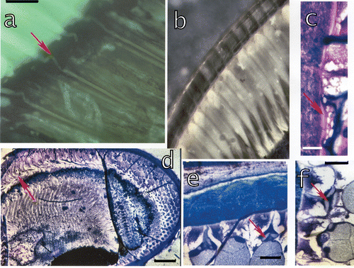
Figure 7. a, Section of a dark‐adapted retina of L. m. seen in epifluorescent light (λe = 305 nm) showing the bent connections (arrow) from the cones to the rhabdoms. Bar: 20 µm. b, In the light‐adapted eyes the crystalline cones suddenly restrict to slim proximal parts which enter the retina and contact the rhabdoms. c, In light‐adapted eyes a thin facet (arrow) underlies the corneal facet and may contribute to the reflection. Bar: 20 µm. d, Section through a juvenile eye of L. m. showing the bending of cones in these quickly growing eyes. Bar: 300 µm. e–f, Connecting structures (arrows) between the cornea and the crystalline cones in a growing eye of S. mantis. These structures possibly form later on the enforcements around the distal tips of the cones. Bar in e 100 µm, in f 50 µm.

Figure 8. a, Eyes of an Alima hyalina larva. Bar: 420 µm. b, Eyes of a squilloid larva. Bar: 500 µm. c, The interior of the eye of the squilloid larva. The arrow indicates the little rooflets hanging from the cornea and covering the distal tips of the crystalline cones. Bar: 100 µm. d–e, Postlarval eye of Pseudosquillopsis marmorata. d, Seen from the larval (left) towards the adult (right) eye, e, the adult double eye in the foreground. Bars: 105 µm. f, Adult eye of L. maculata. Bar: 2 mm. Arrows in d and f indicate the morphogenetic furrows in the postlarval and in the adult eye.
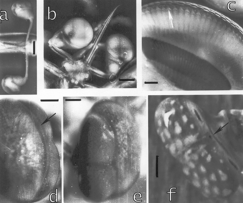
Figure 8. a, Eyes of an Alima hyalina larva. Bar: 420 µm. b, Eyes of a squilloid larva. Bar: 500 µm. c, The interior of the eye of the squilloid larva. The arrow indicates the little rooflets hanging from the cornea and covering the distal tips of the crystalline cones. Bar: 100 µm. d–e, Postlarval eye of Pseudosquillopsis marmorata. d, Seen from the larval (left) towards the adult (right) eye, e, the adult double eye in the foreground. Bars: 105 µm. f, Adult eye of L. maculata. Bar: 2 mm. Arrows in d and f indicate the morphogenetic furrows in the postlarval and in the adult eye.

Figure 9. a, The tissue at the interior of the morphogenetic furrow in a section across the midband. From this proliferation tissue little tree‐like extensions (arrowhead) grow towards the interior of the eye. Bar: 100 µm. b, The tissue is organised in hexagonal patterns, typical for the stomatopod eye. Each group produces the veils surrounding the cones. Bar: 10 µm. c, Formation of networks generating the veils around the cones. bar: 20 µm. d, The extensions originating in each of the groups in b contact a network generating myofibril‐containing veils. Myofibrils are already present (arrow). Arrowhead: generation of a corneagenous cell in the network at the contact region with the tissue. Bar: 20 µm. e–f, Extensions from the tissue which have already formed two corneagenous cells, c.c., for each new ommatidium. The corneagenous cells form the crystalline cones (arrows), besides the new cornea. Bars: 50 µm.
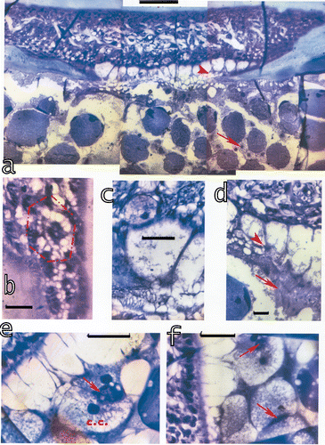
Figure 9. a, The tissue at the interior of the morphogenetic furrow in a section across the midband. From this proliferation tissue little tree‐like extensions (arrowhead) grow towards the interior of the eye. Bar: 100 µm. b, The tissue is organised in hexagonal patterns, typical for the stomatopod eye. Each group produces the veils surrounding the cones. Bar: 10 µm. c, Formation of networks generating the veils around the cones. bar: 20 µm. d, The extensions originating in each of the groups in b contact a network generating myofibril‐containing veils. Myofibrils are already present (arrow). Arrowhead: generation of a corneagenous cell in the network at the contact region with the tissue. Bar: 20 µm. e–f, Extensions from the tissue which have already formed two corneagenous cells, c.c., for each new ommatidium. The corneagenous cells form the crystalline cones (arrows), besides the new cornea. Bars: 50 µm.

Figure 10. Sections parallel to the midband at the morphogenetic furrow show the proliferation tissue generating the dioptric apparatus at its distal part and the formation of the retina at its proximal part.a, Extending from the cornea are the myofibril containing veils and the corneagenous cells containing the beginning of a cone at their interior. The balls of black pigment are presumably the beginning of the formation of the accessory pigment cells. Black pigment surrounds also the beginning of the first‐order nerve fibres, i.e. the continuation of the retinular cells after passage through the basement membrane which last is also generated here. Bar: 100 µm. b–c, The corneagenous cells and the veils are already formed and generate the cones at their interior. Cone formation is advanced in b in the beginning in c; bar in b: 50 µm, in c: 100 µm. d, Contact between the new cone and the rhabdom and the formation of the four cone extensions which then attach to the basement membrane. Bar: 20 µm. e, The new connections between the dioptric and the retinal part. The myofibril containing ‘veils’ attach to the accessory pigment cells, but are still undulated (arrows). These structures will be stretched later on, presumably once the cone extensions and the accessory pigment cells are attached to the basement membrane. Bar: 20 µm.
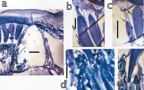
Figure 10. Sections parallel to the midband at the morphogenetic furrow show the proliferation tissue generating the dioptric apparatus at its distal part and the formation of the retina at its proximal part.a, Extending from the cornea are the myofibril containing veils and the corneagenous cells containing the beginning of a cone at their interior. The balls of black pigment are presumably the beginning of the formation of the accessory pigment cells. Black pigment surrounds also the beginning of the first‐order nerve fibres, i.e. the continuation of the retinular cells after passage through the basement membrane which last is also generated here. Bar: 100 µm. b–c, The corneagenous cells and the veils are already formed and generate the cones at their interior. Cone formation is advanced in b in the beginning in c; bar in b: 50 µm, in c: 100 µm. d, Contact between the new cone and the rhabdom and the formation of the four cone extensions which then attach to the basement membrane. Bar: 20 µm. e, The new connections between the dioptric and the retinal part. The myofibril containing ‘veils’ attach to the accessory pigment cells, but are still undulated (arrows). These structures will be stretched later on, presumably once the cone extensions and the accessory pigment cells are attached to the basement membrane. Bar: 20 µm.

Reprints and Corporate Permissions

Please note: Selecting permissions does not provide access to the full text of the article, please see our help page How do I view content?

To request a reprint or corporate permissions for this article, please click on the relevant link below:

Academic Permissions

Please note: Selecting permissions does not provide access to the full text of the article, please see our help page How do I view content?

Obtain permissions instantly via Rightslink by clicking on the button below:

If you are unable to obtain permissions via Rightslink, please complete and submit this Permissions form. For more information, please visit our Permissions help page.