3,438
Views
68
CrossRef citations to date
0
Altmetric
Recent Advances in Woody Root Research

Towards developmental modelling of tree root systems

, , , , , , , , , , , , , & show all
Pages 481-501 | Published online: 15 Nov 2007

Figures & data

Figure 1. A graphical reconstruction from 3D digitised data of a 12-year-old Pinus pinaster root system grown in a sandy spodosol, using AMAPmod. Tree 5307 from the dataset used in Danjon et al. (Citation2006) seen from the South with 25 cm collar diameter. The root system was uprooted by lifting the stump from the soil. All roots with a base diameter larger than 0.2 cm were measured. The solid line marks the soil level; the maximum rooting depth was 1 m.
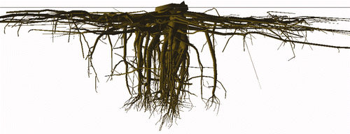
Figure 1. A graphical reconstruction from 3D digitised data of a 12-year-old Pinus pinaster root system grown in a sandy spodosol, using AMAPmod. Tree 5307 from the dataset used in Danjon et al. (Citation2006) seen from the South with 25 cm collar diameter. The root system was uprooted by lifting the stump from the soil. All roots with a base diameter larger than 0.2 cm were measured. The solid line marks the soil level; the maximum rooting depth was 1 m.

Figure 2. Transpiration rates of species with contrasting rooting depth (shallow: Picea abies, and deep: Pinus sylvestris) under changing soil moisture conditions in surface and deep soil horizons (Čermák et al., Citation1992). Variation between individual trees is expressed as a percentage of the mean.
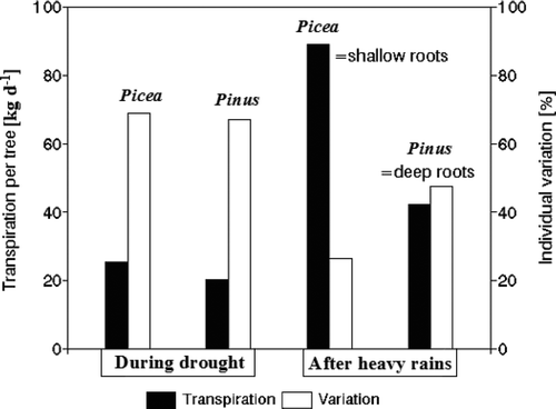
Figure 2. Transpiration rates of species with contrasting rooting depth (shallow: Picea abies, and deep: Pinus sylvestris) under changing soil moisture conditions in surface and deep soil horizons (Čermák et al., Citation1992). Variation between individual trees is expressed as a percentage of the mean.

Figure 3. Panel A: Sap flow density across stem cross sections in Scots pine measured by the heat field deformation (HFD) method using 48 measuring points along the stem circumference (Čermák et al., Citation2004). Panel B: An interpretation of the radial pattern of sap flow from stemwood of Pinus sylvestris trees measured using HFD sensors. Sap flow in outer sapwood layers has been shown to originate more from superficial roots and flow in inner sapwood layers more from the taproot and sinker roots directly branched off the stump or from superficial roots growing several meters from the stem (Nadezhdina et al., Citation2007). The dotted line mean curve was measured; the curves with triangles are an interpretation of the dotted curve. An applied mathematical curve separation procedure indicates approximately the probable involvement of superficial and sinker roots in the whole-tree water supply (with large natural overlapping).
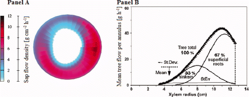
Figure 3. Panel A: Sap flow density across stem cross sections in Scots pine measured by the heat field deformation (HFD) method using 48 measuring points along the stem circumference (Čermák et al., Citation2004). Panel B: An interpretation of the radial pattern of sap flow from stemwood of Pinus sylvestris trees measured using HFD sensors. Sap flow in outer sapwood layers has been shown to originate more from superficial roots and flow in inner sapwood layers more from the taproot and sinker roots directly branched off the stump or from superficial roots growing several meters from the stem (Nadezhdina et al., Citation2007). The dotted line mean curve was measured; the curves with triangles are an interpretation of the dotted curve. An applied mathematical curve separation procedure indicates approximately the probable involvement of superficial and sinker roots in the whole-tree water supply (with large natural overlapping).

Table I. Examples of allometric models (covering different species) for estimating root system biomass (kg dry matter) as the function of DBH (cm) of single trees

Figure 4. Single-tree root system biomass (excl. fine roots) as a function of DBH for Pinus sylvestris growing on deep peat. Data from various sources across Fennoscandia. Open symbols represent trees from drained but otherwise unmanaged stands; filled symbols represent trees from fertilized (Finér, Håland & Braekke, Vasander) or thinned (Penttilä & Laiho) plots. The curve shows the fit of the model y = 0.013 DBH2.74 (R 2 = 0.99) developed by Laiho & Finér (Citation1996) using the unmanaged trees of Finér (Citation1989, Citation1991), Håland & Braekke (Citation1989) and Vasander (1982) from southern Fennoscandia. Data of Penttilä & Laiho are from northern Finland. If only the range of DBH values inside the dotted lines (excluding data from the small and large ends of the range) are available, simple linear regression will produce an equally good fit and the relationship would appear to be simply linear.
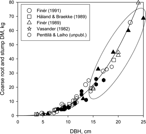
Figure 4. Single-tree root system biomass (excl. fine roots) as a function of DBH for Pinus sylvestris growing on deep peat. Data from various sources across Fennoscandia. Open symbols represent trees from drained but otherwise unmanaged stands; filled symbols represent trees from fertilized (Finér, Håland & Braekke, Vasander) or thinned (Penttilä & Laiho) plots. The curve shows the fit of the model y = 0.013 DBH2.74 (R 2 = 0.99) developed by Laiho & Finér (Citation1996) using the unmanaged trees of Finér (Citation1989, Citation1991), Håland & Braekke (Citation1989) and Vasander (1982) from southern Fennoscandia. Data of Penttilä & Laiho are from northern Finland. If only the range of DBH values inside the dotted lines (excluding data from the small and large ends of the range) are available, simple linear regression will produce an equally good fit and the relationship would appear to be simply linear.

Figure 5. Analysis of root cross sectional shape. Left, Typical spruce I- and T-beam root cross sectional shapes. Right, a. A system for measurement of such sections relative to ‘bc’, the biological centre, and b. analysis of the development of I-beam (I angle) and T-beam shapes (T angle), from Nicoll & Ray (Citation1996).
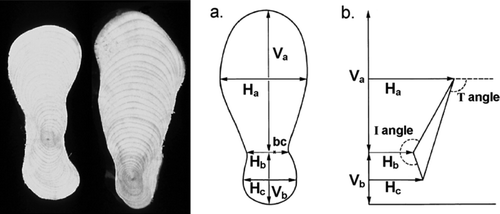
Figure 5. Analysis of root cross sectional shape. Left, Typical spruce I- and T-beam root cross sectional shapes. Right, a. A system for measurement of such sections relative to ‘bc’, the biological centre, and b. analysis of the development of I-beam (I angle) and T-beam shapes (T angle), from Nicoll & Ray (Citation1996).

Figure 6. The link between coarse and fine root development. Modified from a conceptual model proposed by Coutts et al. (Citation1999).
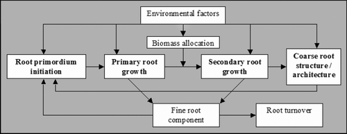
Figure 6. The link between coarse and fine root development. Modified from a conceptual model proposed by Coutts et al. (Citation1999).

Reprints and Corporate Permissions

Please note: Selecting permissions does not provide access to the full text of the article, please see our help page How do I view content?

To request a reprint or corporate permissions for this article, please click on the relevant link below:

Academic Permissions

Please note: Selecting permissions does not provide access to the full text of the article, please see our help page How do I view content?

Obtain permissions instantly via Rightslink by clicking on the button below:

If you are unable to obtain permissions via Rightslink, please complete and submit this Permissions form. For more information, please visit our Permissions help page.