Figures & data
Figure 1. Schematic image of a film-stack reaction field with a micro-pillars array in a well of a 96-well microtitre plate.
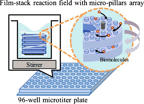
Figure 2. Optical images of the film-stack reaction field with a micro-pillars array: top view (a); side view (b). The outside diameter and the central-hole diameter were 5.0 and 2.0 mm, respectively. The height from a top film to a bottom magnetic sheet is approximately 3.0 mm. The space between the films is 10 μm, which depends on the height of a micro-pillar.
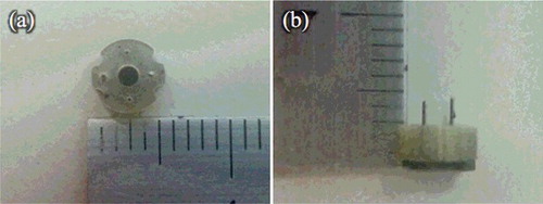
Table 1. Structural dimensions of the micro-pillars array.
Figure 3. SEM images of micro-pillars array on the film. The diameters and heights of the micro-pillars are 50 and 10 μm, respectively. The gaps between the micro-pillars are 5 μm (a), 10 μm (b) and 50 μm (c).
Figure 4. Geometry models in the fluid-flow analysis and the particle trajectory analysis. A whole well (a) with a film-stack reaction field; a micro-channel (b) with different dimensions of micro-pillars array on a film; a circular tube (c) with hydrodynamic diameter dhydro. dfilm and dhole are the outside diameter and the central-hole diameter of a film, respectively; dhydro is calculated using the diameter and the gap of the micro-pillars array.
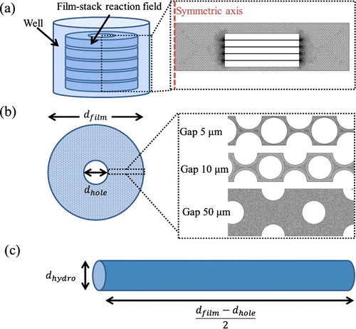
Figure 5. Conceptual image of the micro-channel model and the circular-tube model. The space between films is assumed to be composed of multiple micro-channels. The number of micro-channels depends on the structural dimensions of the micro-pillars array. A circular tube with hydrodynamic diameter is the simplified model of a micro-channel with a micro-pillars array.
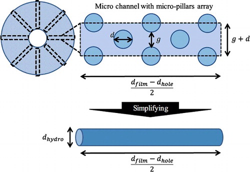
Table 2. Conditions used in the fluid-flow analysis in all models.
Table 3. Conditions used in the particle trajectory analysis.
Figure 6. Fluorescence intensities at two incubation times for HRP-IgA in wells with or without film-stack reaction fields with different dimensions of micro-pillars array (N = 3).
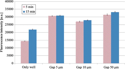
Figure 7. Flow velocity and streamline at the fluidic analysis in the first model of a whole well with a film-stack reaction field: a whole geometry (a); enlarged images (b) and (c), which show the flow velocity vectors. The flow direction is from the central-hole to the outside of a film-stack reaction field. The average velocity between films is 0.43 m/s.
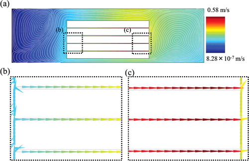
Figure 8. Fluid velocity and streamline of micro-channels with different dimensions of micro-pillars array using the second model (a); average flow velocity between micro-pillars with different dimensions (b). The inlet velocity of all channels is 0.43 m/s, which is the average velocity between films calculated by the first model as shown in .
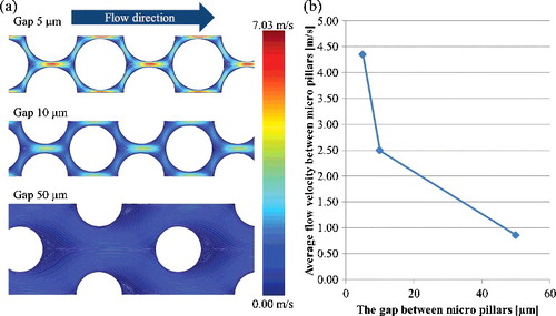
Figure 9. Number of adsorbed biomolecule particles in a circular tube with hydrodynamic diameter by particle trajectory analysis in the third model.
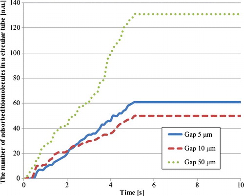
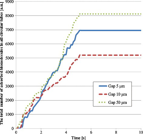
Figure 10. Total number of adsorbed biomolecule particles in all circular tubes. This number was calculated by multiplying the number of adsorbed biomolecule particles in a circular tube by the number of circular tubes per space between films as shown in EquationEquation (8(8)
(8) ). There are 114 circular tubes in the 5-μm gap, 105 ones in the 10-μm gap and 63 ones in the 50-μm gap.