
Figures & data
Table 1. Categories of bioaerosol samplers.
Figure 1. Cyclone with swirling spiral pattern (Reused from Peng et al. [Citation31] with permission).
![Figure 1. Cyclone with swirling spiral pattern (Reused from Peng et al. [Citation31] with permission).](/cms/asset/b60772ad-7114-4a19-918b-6424c051051e/tbeq_a_1797529_f0001_c.jpg)
Figure 2. WWC-1250 device with four modifications by McFarland et al. [Citation32] [Reused with permission]. Red circled numbers: the aerosol inlet of the upgraded device forms a converging flow path into the cyclone,
the liquid is atomized before entering the inlet slot of this device,
the length of the cylindrically shaped cyclone body is shorter, and
the skimmer was changed to a straight shape rather than a divergent opening.
![Figure 2. WWC-1250 device with four modifications by McFarland et al. [Citation32] [Reused with permission]. Red circled numbers: 1 the aerosol inlet of the upgraded device forms a converging flow path into the cyclone, 2 the liquid is atomized before entering the inlet slot of this device, 3 the length of the cylindrically shaped cyclone body is shorter, and 4 the skimmer was changed to a straight shape rather than a divergent opening.](/cms/asset/7a610a63-dddf-49f6-9cae-ee9810511c05/tbeq_a_1797529_f0002_c.jpg)
Figure 3. Virtual cyclone. Left: airflow in the virtual sampler (Reused from Haig et al. [Citation28] with permission). Right: schematic of a virtual cyclone (Reused from Song et al. [Citation20] with permission).
![Figure 3. Virtual cyclone. Left: airflow in the virtual sampler (Reused from Haig et al. [Citation28] with permission). Right: schematic of a virtual cyclone (Reused from Song et al. [Citation20] with permission).](/cms/asset/718a40bb-50e4-4ec2-977c-2439cbdd317b/tbeq_a_1797529_f0003_c.jpg)
Figure 4. Recent commercial bioaerosol cyclones: Coriolis®µ (a), Research International SASS2300 (b), FLIR Systems BioCapture650 (c), Dekati S110 (d), Burkard C90M (e) and Fuji Biotechnology BIO-Capturer-6 (f).
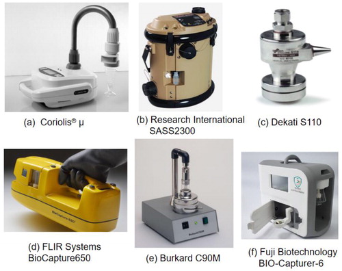
Figure 5. Venn diagram of the three cyclone performance parameters associated with the inlet efficiency, transport efficiency, and deposition efficiency. (1) Yellow: the common factors associated with all parameters. These are the sampled air-flow rate, particle concentration in the air stream, and particle size. (2) Blue: common factors between the inlet and deposition efficiencies. These are the particle concentrations in the air at the inlet. (3) Pink: common factors between the sampling and deposition efficiencies. These are particle concentrations in the liquid medium. (4) Green: common factors between the inlet and transport efficiencies. These are sampled with the air flow rate [Citation8].
![Figure 5. Venn diagram of the three cyclone performance parameters associated with the inlet efficiency, transport efficiency, and deposition efficiency. (1) Yellow: the common factors associated with all parameters. These are the sampled air-flow rate, particle concentration in the air stream, and particle size. (2) Blue: common factors between the inlet and deposition efficiencies. These are the particle concentrations in the air at the inlet. (3) Pink: common factors between the sampling and deposition efficiencies. These are particle concentrations in the liquid medium. (4) Green: common factors between the inlet and transport efficiencies. These are sampled with the air flow rate [Citation8].](/cms/asset/fac1b9b3-ae65-4be9-83a7-99f5cecfae7a/tbeq_a_1797529_f0005_c.jpg)
Figure 6. Modifications in aerosol-to-hydrosol cyclone based on CFD simulations (Reused from Hu & McFarland [Citation16] with permission): narrowing the rectangular entrance slot,
narrowing the shape of air-flow inlet,
adding water injection at the top of cyclone inlet,
changing to a rectangular cyclone body and
re-designing the shape of the cyclone skimmer in the rectangular region.
![Figure 6. Modifications in aerosol-to-hydrosol cyclone based on CFD simulations (Reused from Hu & McFarland [Citation16] with permission): 1 narrowing the rectangular entrance slot, 2 narrowing the shape of air-flow inlet, 3 adding water injection at the top of cyclone inlet, 4 changing to a rectangular cyclone body and 5 re-designing the shape of the cyclone skimmer in the rectangular region.](/cms/asset/97bd9991-7056-4090-8db0-5b68fdacb0ff/tbeq_a_1797529_f0006_c.jpg)
Figure 7. Integrated scheme for development of an ideal design of a cyclone.
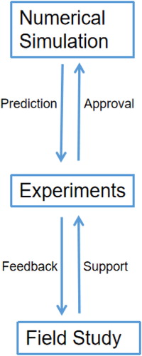
Table 2. Listing of various geometric design units for the cyclone sampling system.