1,235
Views
0
CrossRef citations to date
0
Altmetric
Agronomy & Crop Ecology

Growth behavior of suckers derived from transplanted sago palm (Metroxylon sagu Rottb.)

, , &
Pages 340-347 | Received 03 Nov 2015, Accepted 04 Jan 2016, Published online: 15 Mar 2016

Figures & data

Figure 1. Base of the MS (a) and an upper view of the MS (b) at about one year after transplantation. MS stands for main stem. Blue pole in (a) and the star symbol in (b) show the reference point (OM). S1 and S2 are primary suckers that appeared from MS; OP–S1 and OP–S2 denote the appearance positions from MS. ▶▶▶ indicates the creeping direction of MS. Rosy arrows indicate the creeping directions of S1 and S2.(a): Rosy dashed line ( – ) shows the creeping part of MS and (b): dS1 and dS2, respectively, denote the distances from OM to OP–S1 and OP–S2. θS1 and θS2 are angles of their creeping direction subtended by the creeping direction of MS.
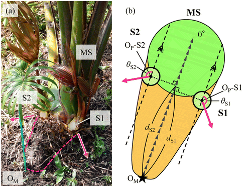
Figure 1. Base of the MS (a) and an upper view of the MS (b) at about one year after transplantation. MS stands for main stem. Blue pole in (a) and the star symbol in (b) show the reference point (OM). S1 and S2 are primary suckers that appeared from MS; OP–S1 and OP–S2 denote the appearance positions from MS. ▶▶▶ indicates the creeping direction of MS. Rosy arrows indicate the creeping directions of S1 and S2.(a): Rosy dashed line ( – ) shows the creeping part of MS and (b): dS1 and dS2, respectively, denote the distances from OM to OP–S1 and OP–S2. θS1 and θS2 are angles of their creeping direction subtended by the creeping direction of MS.

Figure 2. Relation between the distance from appearance positions of each primary sucker to OM and the angles of their creeping direction. n = 131.
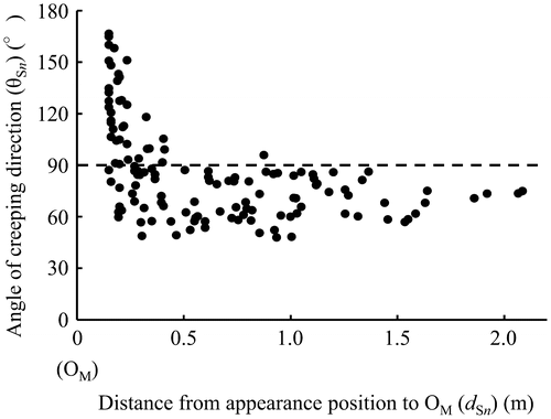
Figure 2. Relation between the distance from appearance positions of each primary sucker to OM and the angles of their creeping direction. n = 131.

Figure 3. Frequency distribution of appearance positions in primary suckers. The frequency distribution is shown every 0.05 m from OM. n = 131.
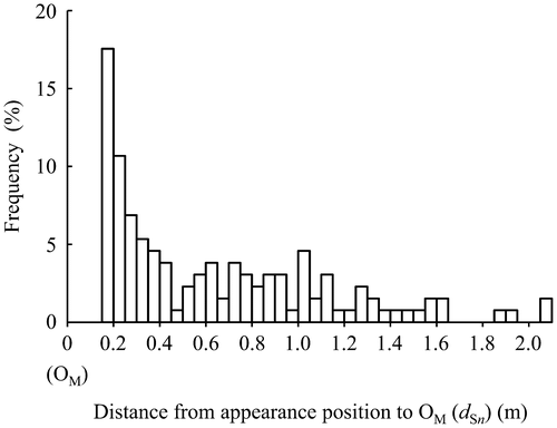
Figure 3. Frequency distribution of appearance positions in primary suckers. The frequency distribution is shown every 0.05 m from OM. n = 131.

Figure 4. Relation between the order of appearing positions of primary suckers on MS and their creeping direction. Error bars show the standard deviation. The same letter represents no significance at the 5% level by Tukey’s test.
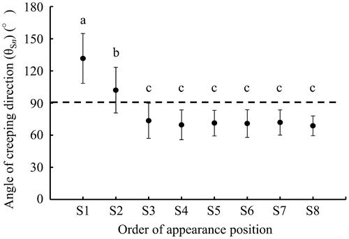
Figure 4. Relation between the order of appearing positions of primary suckers on MS and their creeping direction. Error bars show the standard deviation. The same letter represents no significance at the 5% level by Tukey’s test.

Figure 5. Diagram of the creeping direction and the length in the creeping part of primary suckers. The side attached S1 is regarded as a positive angle. Dashed lines ( – ) show the creeping direction of MS. The thick solid line (—) shows the creeping direction and the length of the primary sucker. Circles around OM, respectively, denote 1.0 m and 2.0 m in distance from OM.

Figure 5. Diagram of the creeping direction and the length in the creeping part of primary suckers. The side attached S1 is regarded as a positive angle. Dashed lines ( – ) show the creeping direction of MS. The thick solid line (—) shows the creeping direction and the length of the primary sucker. Circles around OM, respectively, denote 1.0 m and 2.0 m in distance from OM.

Figure 6. Relation between the distance from appearing position of each secondary sucker to OP and the angles of their creeping direction. *Indicates S2–1 of plant D presented in Figure . n = 110.
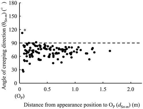
Figure 6. Relation between the distance from appearing position of each secondary sucker to OP and the angles of their creeping direction. *Indicates S2–1 of plant D presented in Figure 8. n = 110.

Figure 7. Diagram of the creeping direction and the length in the creeping part of secondary suckers. The side on which Sn-1 was attached was regarded as a positive angle. The dashed line ( – ) shows the creeping direction of the mother stem. The thick solid line (—) shows the creeping direction and the secondary sucker length. The length is represented with a logarithmic scale. The outside circle and the inside circle around OP, respectively, denote 1.0 m and 0.1 m in distance from OP.

Figure 7. Diagram of the creeping direction and the length in the creeping part of secondary suckers. The side on which Sn-1 was attached was regarded as a positive angle. The dashed line ( – ) shows the creeping direction of the mother stem. The thick solid line (—) shows the creeping direction and the secondary sucker length. The length is represented with a logarithmic scale. The outside circle and the inside circle around OP, respectively, denote 1.0 m and 0.1 m in distance from OP.

Figure 8. Growth behavior of MS and derivative suckers in a part of experimental section at about nine years after transplantation. Circles denote the positions of MS and derivative suckers which expanded leaves. The circle size denotes the stem or trunk diameter. Gray circles denote MS and derivative suckers from the trunk formation stage to the trunk elongation stage. A star denotes the reference point (OM). The thick line ( – ) and the fine line (―), respectively, show the creeping parts of MS and derivative suckers.
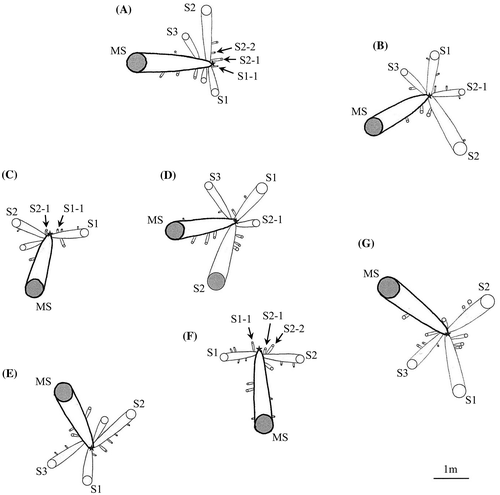
Figure 8. Growth behavior of MS and derivative suckers in a part of experimental section at about nine years after transplantation. Circles denote the positions of MS and derivative suckers which expanded leaves. The circle size denotes the stem or trunk diameter. Gray circles denote MS and derivative suckers from the trunk formation stage to the trunk elongation stage. A star denotes the reference point (OM). The thick line ( – ) and the fine line (―), respectively, show the creeping parts of MS and derivative suckers.

Figure 9. Area where leaves attach in the creeping growth stage. The white arrow indicates the creeping direction of the mother stem. The dashed line (—) shows the estimated nodal plane. The dashed arrow indicates the creeping direction when the daughter sucker appeared.
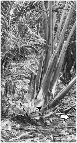
Figure 9. Area where leaves attach in the creeping growth stage. The white arrow indicates the creeping direction of the mother stem. The dashed line (—) shows the estimated nodal plane. The dashed arrow indicates the creeping direction when the daughter sucker appeared.

Figure 10. Distribution of trunks of MS and prediction position of trunks of derivative suckers. The gray circles show the positions of suckers that already formed a trunk. White circles show the prediction positions of suckers forming a trunk. The star denotes the reference point (OM). The circle size and the length from OM were estimated from the size of suckers that already formed a trunk.
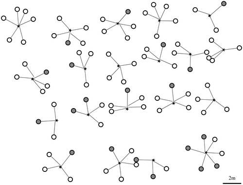
Figure 10. Distribution of trunks of MS and prediction position of trunks of derivative suckers. The gray circles show the positions of suckers that already formed a trunk. White circles show the prediction positions of suckers forming a trunk. The star denotes the reference point (OM). The circle size and the length from OM were estimated from the size of suckers that already formed a trunk.