Figures & data
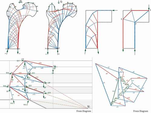
Figure 1. Structures developing from self-forming processes, classified according to the generated forces (Gaß Citation2016).
Figure 2. Framework of the methodology.
Figure 3. Femur head principal stress representation (Stoltz et al. Citation2018) and the force condition of the femur in human body.
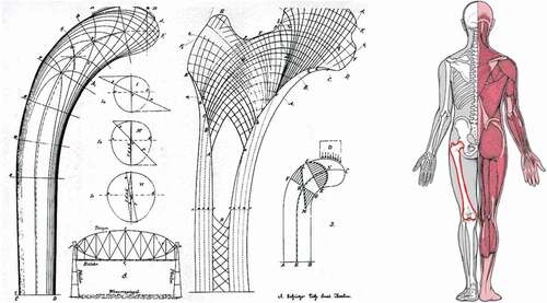
Figure 4. The solution of layout optimization inside the .
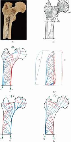
Figure 5. Simplified boundary and LAYOPT result.
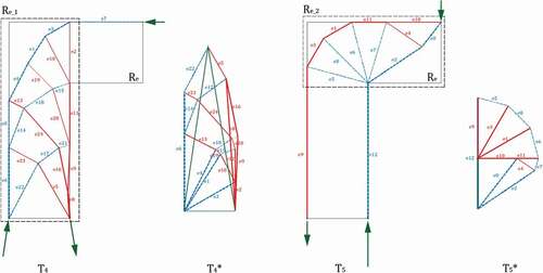
Figure 6. The Michell Cantilever simplifying process with the Morph method from Meng.
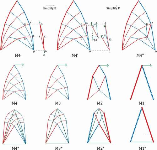
Figure 7. Combining two optimized model to make the basic structural principle unit (BSPU) .
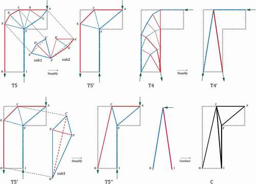
Figure 8. Stability test under multi-directional loads.
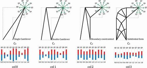
Figure 9. The new structural prototype model generated from self-combination of one BSPU.
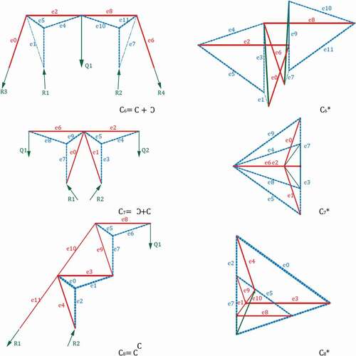
Figure 10. structure principle derivation by graphic static.
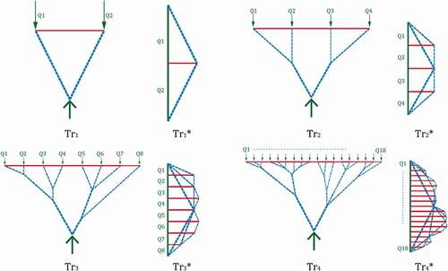
Figure 11. The new structural prototype model generated from combining two different BSPUs.
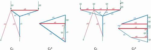
Figure 12. The diagram of the preconditions of the stadium (left); The BSPU applied to the design (right).
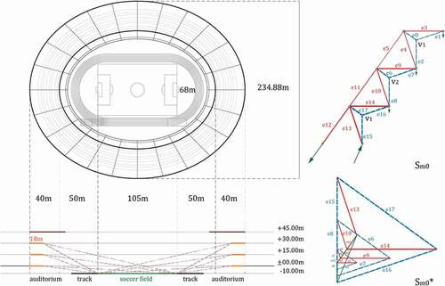
Figure 13. Stadium section form finding by transformation method in graphic static.
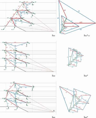
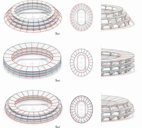
Figure 14. The statistics of the three configurations.
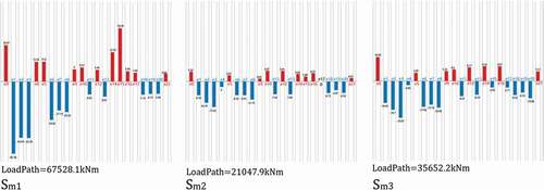
Figure 15. Stadium space based on three structural solutions.