Figures & data
Figure 1. Structure of a combination and an analogous model: (a) The fundamental bolted flange joint; and (b) The bolted flange joint’s corresponding axial double spring-bending beam model.
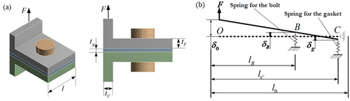
Table 1. Component’s material parameter.
Figure 2. Experiment on the compressive-resilient performance of cylinder gasket.
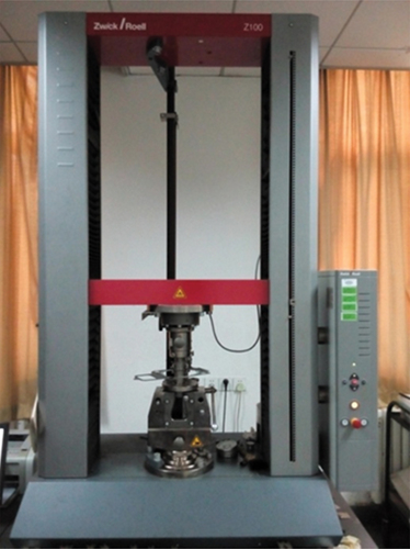
Table 2. Graphite gasket compression resilience test data.
Figure 3. Compressive-resilient performance curves of graphite gasket.
Figure 4. Static finite element calculation of the bolted flange joint: (a) Basic bolted flange joint finite element model and (b) Overall axial deformation (FE).
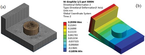
Figure 5. The load-displacement curve of the combination structure: (a) Non-linear materials and (b) Linear elastic material.
Figure 6. Linear and nonlinear spring load-displacement curves.
Figure 7. Linear and nonlinear spring stiffness-displacement curves.
Figure 8. Deformation of the combination structure:(a) the axial tension state (b) the axial compression state.
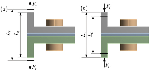
Figure 9. Mass-spring system.
Figure 10. Division of the motion.
Figure 11. Deformation of a double-degree-of-freedom mass-spring system under transverse load.
Table 3. Spring state and stiffness matrix of each vibration area (Luan Citation2012).
Figure 12. The vibration response of the mass-spring two-degree-of-freedom system when the spring stiffness is constant: (a) Displacement response and (b) In-plane response of spring displacement.
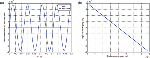
Figure 13. The vibration response of the system under the condition that the spring stiffness is a linear function of displacement and the mass matrix is not coupled: (a) Displacement response and (b) Speed response.
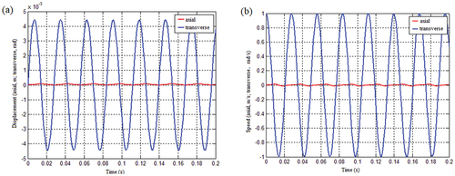
Figure 14. The displacement response of spring 1 and spring 2 under the condition that the mass matrix of spring stiffness is a linear function of displacement is not coupled: (a) Displacement response of springs and (b) The displacement response of springs when the initial angular velocity is 1 rad/s.
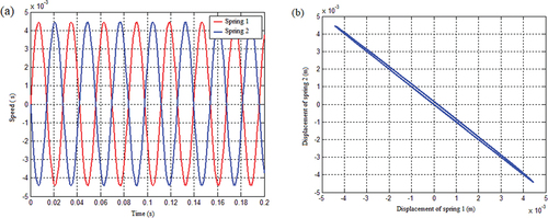
Figure 15. The vibration response of the system in the plane, under the condition that the spring stiffness is a linear function of displacement and the mass matrix of the system is not coupled, when the initial angular velocity is (a) 0.5 rad/s, (b) 2 rad/s, (c) 3 rad/s, and (d) 5 rad/s.
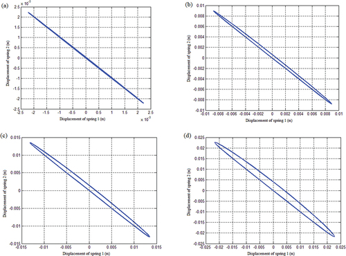
Figure 16. Vibration response of spring 1 and spring 2 under the condition that the mass matrix of the system with a given initial velocity of spring 1 is not coupled: (a) Displacement response and (b) Speed response.
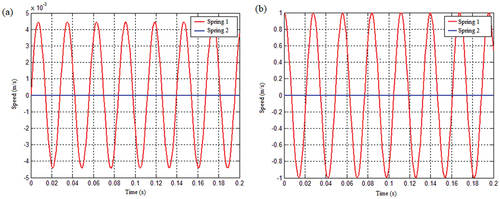
Figure 17. Vibration response of the system under the coupling condition of the linear function mass matrix with spring stiffness as displacement: (a) displacement response and (b) Speed response.
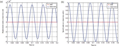
Figure 18. Displacement response of spring 1 and spring 2 under the coupling condition of the mass matrix with a linear function of spring stiffness as displacement: (a) Displacement response of spring 1 and spring 2 and (b) Displacement response of spring 1 and spring 2 when the initial angular velocity is 1 rad/s.
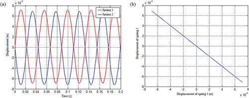
Figure 19. The displacement response of the spring in the plane under the coupling condition of the mass matrix of the linear function the system with spring stiffness as displacement when the initial angular velocity is (a)0.5 rad/s, (b)2 rad/s, (c)3 rad/s, and (d)5 rad/s.
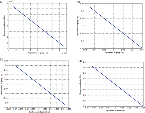
Figure 20. The vibration response of the spring under the coupling condition of the mass matrix of the system with the given initial velocity of spring 1: (a) Displacement response and (b) Speed response.
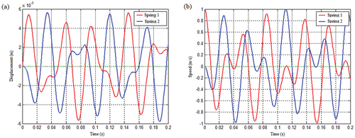
Figure 21. The calculation process of the mechanism model under the bilinear stiffness axial and transverse coupled impact.
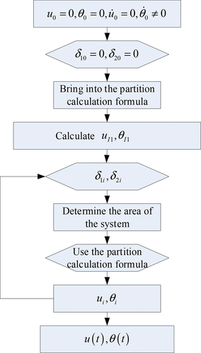
Figure 22. The spring stiffness is the vibration response of the system under the condition of bilinear tension and compression: (a) Axial and transverse vibration displacement response and (b) Axial and transverse vibration speed response.
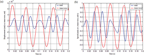
Figure 23. The spring stiffness is the vibration response of the spring under the condition of bilinear tension and compression: (a) Displacement response and b) Displacement relationship.
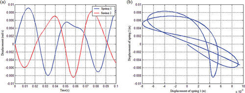
Figure 24. Vibration response of the system in the axial and transverse planes.
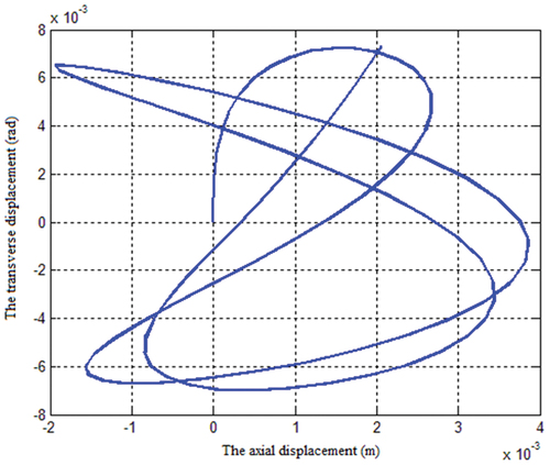
Figure 25. Axial and transverse displacement response of tension and compression bilinear stiffness spring of the connecting cylindrical shell radius L: (a) L = 0.4, (b) L = 0.5, (c) L = 0.9, (d) L = 1, (e) L = 2 and (f) L = 4.
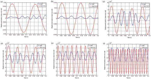
Figure 26. Vibration response of the system under the uncoupled condition of quadratic function mass matrix with spring stiffness as displacement: (a) Axial and transverse displacement response and (b) Axial and transverse velocity response.
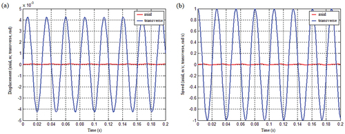
Figure 27. The spring displacement response under the condition that the spring stiffness is the quadratic function of displacement and the mass matrix is not coupled: (a) Displacement response of spring 1 and spring 2 and (b) The displacement response of the spring when the initial angular velocity is 1 rad/s.
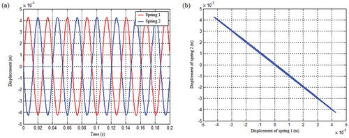
Figure 28. The displacement response of the spring in the plane under the condition that the mass matrix of the quadratic function system with spring stiffness as displacement is not coupled, when the initial angular velocity is (a) 0.5 rad/s, (b)2 rad/s, (c)3 rad/s, and (d) 5 rad/s.
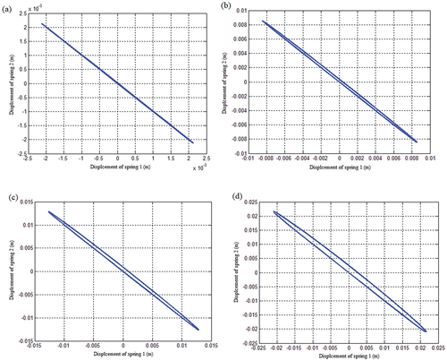
Figure 29. The vibration response of spring 1 and spring 2 under the condition of an uncoupled mass matrix of a quadratic function with spring stiffness as displacement: (a) Spring displacement response and (b) Spring speed response.
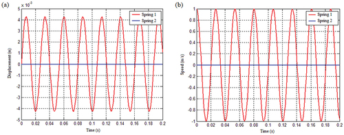
Figure 30. The response of the system under the coupling condition of the quadratic function mass matrix with spring stiffness as displacement: (a) Displacement response and (b) Speed response.
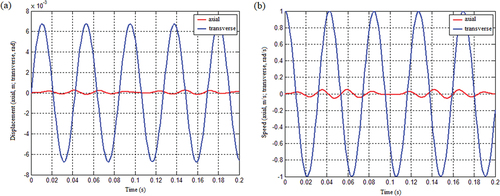
Figure 31. Spring displacement response under the coupling condition of quadratic function mass matrix with spring stiffness as displacement.
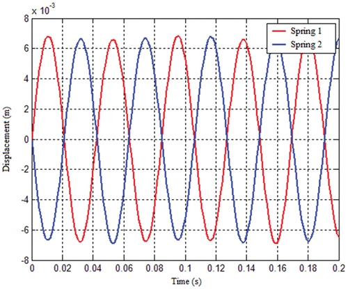
Figure 32. The displacement response of the spring in the plane under the coupling condition of the mass matrix of the quadratic function system with spring stiffness as displacement, when the initial angular velocity is (a) 0.5 rad/s, (b) 1 rad/s, (c) 2 rad/s, and (d) 3 rad/s.
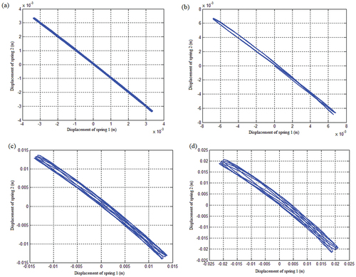
Figure 33. The spring vibration response under the coupling condition of quadratic function mass matrix with spring stiffness as displacement: (a) Displacement response and (b) Speed response.
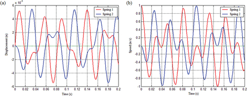
Figure 34. Experimental test layout.
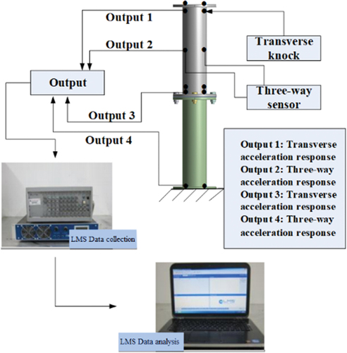
Figure 35. Experimental picture.
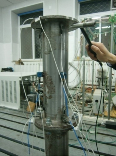
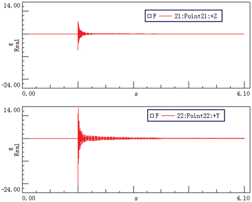
Figure 36. Vibration acceleration response of the bolted flange joint under the transverse impact (the upper picture is axial; the lower picture is transverse).