Figures & data
Figure 1. General arrangement of (a) 40, (b) 60 and (c) 80 m high towers.
Figure 2. Modeling and Analysis of a typical communication tower (a) Line model, (b) 3D computer model, (c) Loading applied.
Table 1. Tower weight and solidity ratio.
Table 2. Effective projected area (EPA)S of each tower segment.
Table 3. Effective projected area (EPA)A of ladder & cable.
Table 4. Design wind force.
Table 5. Design wind force on dishes.
Figure 3. (a) Node interval on one leg, (b) Design wind force on structure, (c) Design wind force on the ladder, cable, and appurtenances, (d & e) Design wind force on antennas, discrete appurtenances.
Figure 4. Leg member forces at wind speed of 125, 225 kph for tower heights 40, 60, and 80 m for (a) Structure Class-I (TIA-222-G), (b) Risk Category-I (TIA-222-H).
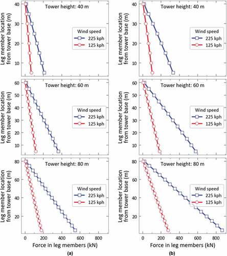
Figure 5. Leg member forces at wind speed of 125, 225 kph for tower heights 40, 60, and 80 m for (a) Structure Class-II (TIA-222-G), (b) Risk Category-II (TIA-222-H).
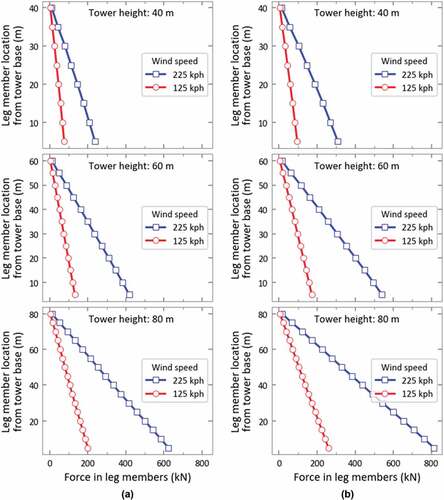
Figure 6. Comparison of forces in leg members for 80 m high tower at basic wind speed of 125 & 225kph for (a) Structure Class-I & II, (b) Risk Category-I & II.
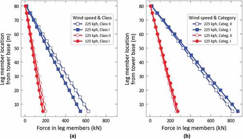
Table 6. Design wind force.
Table 7. Design wind force on dishes.
Table 8. Leg Members compressive, tensile, bolt strength, and utility ratios for 40 m high tower.
Table 9. Tower top maximum displacements.
Figure 7. Comparison of leg member forces for 40, 60 & 80 m high tower and Structure Class-I/Risk Category-I at basic wind speed of 225kph.
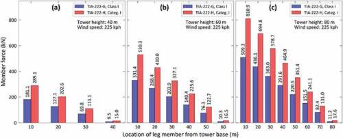
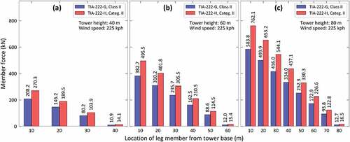
Figure 8. Comparison of leg member forces for 40, 60 & 80 m high tower and Structure Class-II/Risk Category-II at basic wind speed of 225kph.