Figures & data
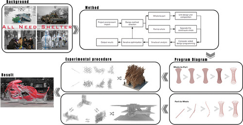
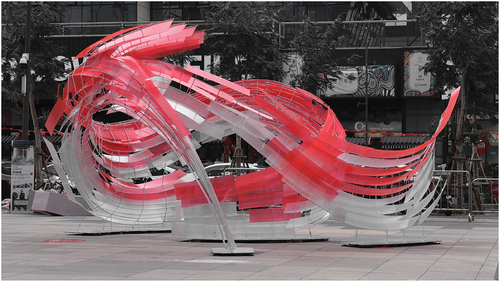
Figure 1. The timeline of weaving theory research and practice.
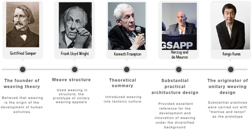
Figure 2. The transformation from continuous to discrete by Greg Lynn’s NURBS curve shows the transition of continuous weaving to unit weaving.
Table 1. Comparing the properties of the unit and intertwine weave forms.
Figure 3. Whole-to-part and part-to-whole design diagrams.
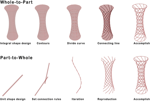
Figure 4. Workflow of unit weaving design.
Figure 5. Woven pavilion of linear units.
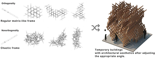
Figure 6. Similar curve unit construction.
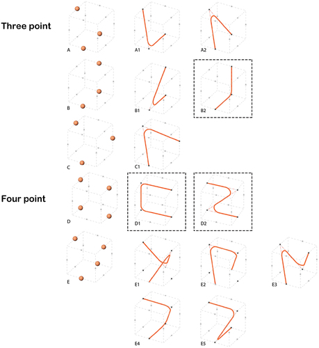
Figure 7. Connection type (knot) of similar curve unit.
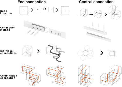
Figure 8. Connection of the curve element after a dimensional change.
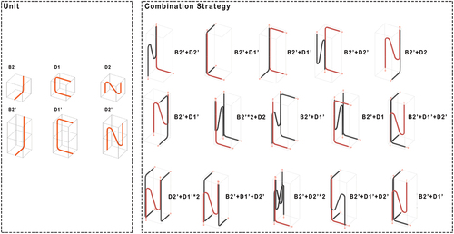
Figure 9. Recycling of curve elements.
Figure 10. Design effect of similar curve weaving.
Figure 11. Based on the surface through the nursery simulation of the curve element.
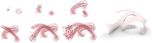
Figure 12. The transformation process from whole-to-part.
Figure 13. 22 Modular elements transformed into a continuous curve by discretisation.
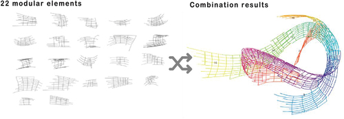
Figure 14. Assessment of material properties based on the project construction location.
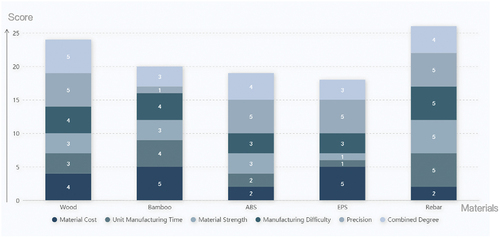
Figure 15. Comparison of the structural displacement before and after replacing different sizes of the rebar tubes.
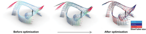
Figure 16. The whole process from manufacturing to assembly.
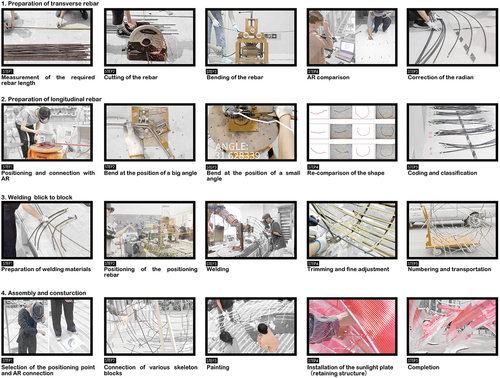
Figure 17. Photo of the woven pavilion display.