Figures & data
Figure 1. Installation of elevator door safety retainers: (a) Guide shoe and stopper and (b) Side hook (ESEMS Website, Citation2023).
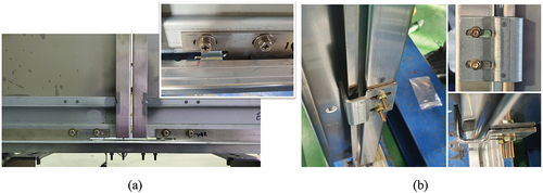
Figure 2. Two types of guide shoes: (a) Flat-type and (b) Hook-type.
Figure 3. Impact test scenarios: (a) Scenario A: 1,000 J at the center of one door and (b) Scenario B: 2,000 J at the center of both doors.
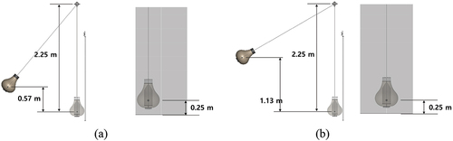
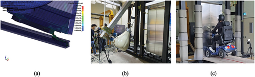
Figure 4. Finite element model of an elevator door with elevator door safety retainers.
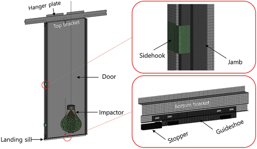
Figure 5. Deformed shape of a door after impact: (a) A1, (b) A2, (c) A3, and (d) B1.
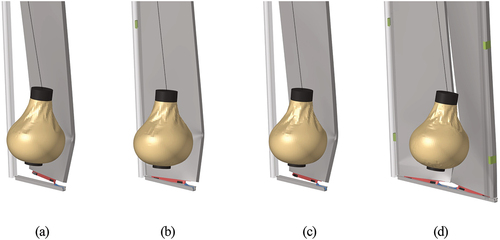
Figure 6. Deformed shape of a guide shoe and stopper after impact: (a) A1, (b) A2, (c) A3, and (d) B1.
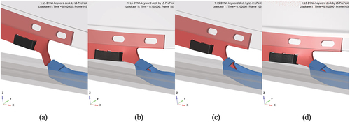
Table 1. Summary of each scenario.
Figure 7. Deformation of each part: (a) Door, (b) Guide shoe, and (c) Stopper.
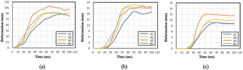
Figure 8. Contour plot of guide shoe: (a) Strain and (b) Stress.
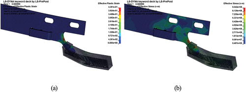
Figure 9. Contour plot of stopper: (a) Strain and (b) Stress.
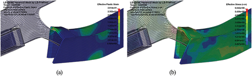
Figure 10. Impact test setup: (a) Installment of the stopper, (b) Installment of the guide shoe, (c) Installment of side hook, (d) Impactor height setup, (e) High-speed camera, and (f) Total impact test setup.
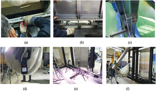
Figure 11. Deformation shape of the stopper after impact: (a) Experiment and (b) Simulation.
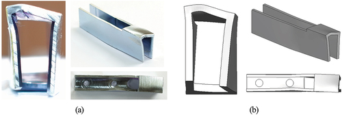
Figure 12. Deformation shape of the guide shoe after impact: (a) Experiment and (b) Simulation.
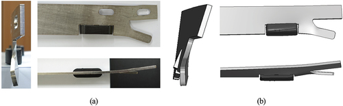
Figure 13. Comparison of the deformation behavior in impact scenario B1: (a) Numerical simulation and (b) Experiment.
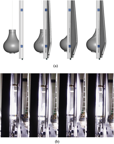
Figure 14. Deformation behavior in the impact scenario with flat-type guide shoes.
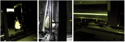
Figure 15. Deformation behavior in the impact scenario with hook-type guide shoes.
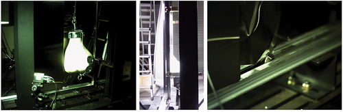
Figure 16. Setup for the impact test with an electric wheelchair: (a) Electric wheelchair, (b) Impact test equipment, and (c) Electric wheelchair with a driver.
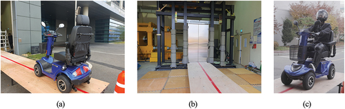
Figure 17. Behavior of the impact test with an electric wheelchair.
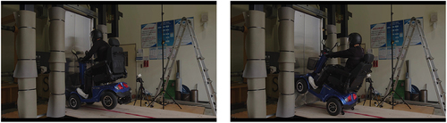
Figure 18. Deformed shape of each part after the impact test: (a) Door, (b) Guide shoe, and (c) Stopper.
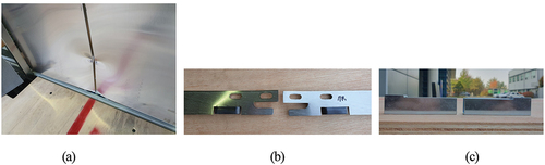
Figure 19. Conclusions of this study: (a) Reliable crash analysis simulation, (b) Verification using impactor test, and (c) Final verification using wheelchair test..