
Figures & data
Figure 1. The coated fabric membrane structure- Shanghai Stadium.
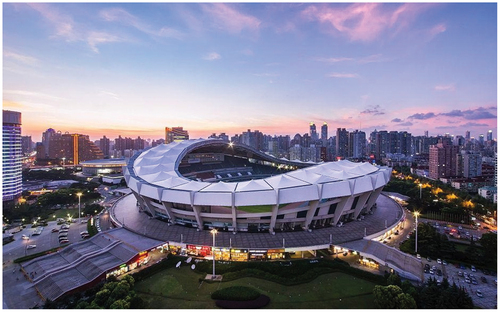
Figure 2. The polymer membrane structure - Eden Project greenhouse.
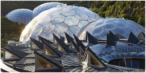
Figure 3. The basic composition of the STFE membrane material.
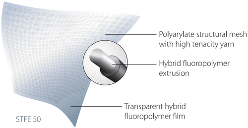
Figure 4. The sparse arrangement of STFE membrane fibers.
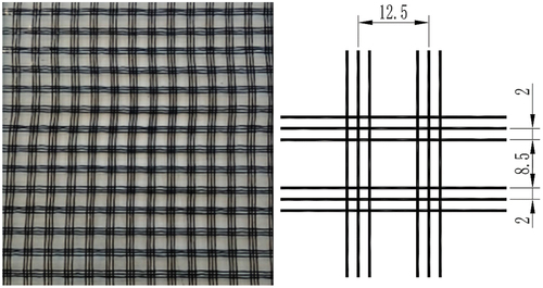
Figure 5. The blurry effect of STFE membrane in structures.
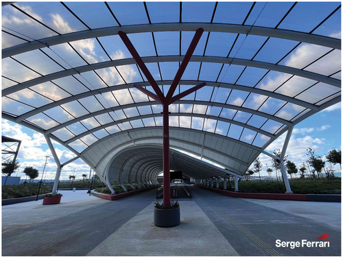
Figure 6. The dimension of the clamping test specimen.
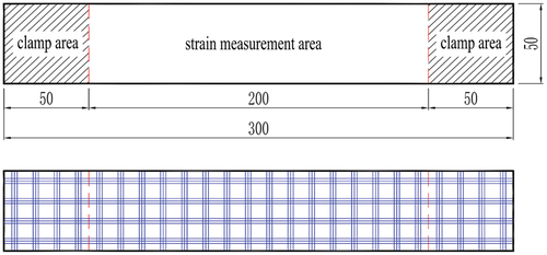
Figure 7. The dimension of the winding test specimen.
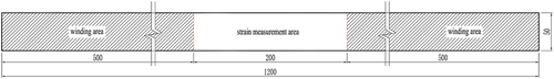
Figure 8. The dimension of the dumbbell-shaped test specimen.
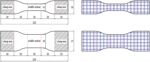
Figure 9. The general clamping test device.
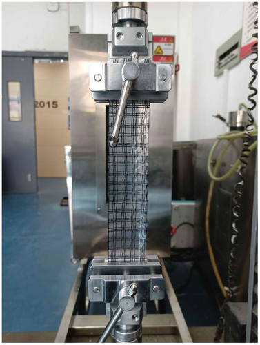
Figure 10. The dumbbell-shaped clamping test device.
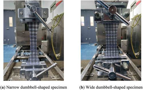
Figure 11. The winding test device.
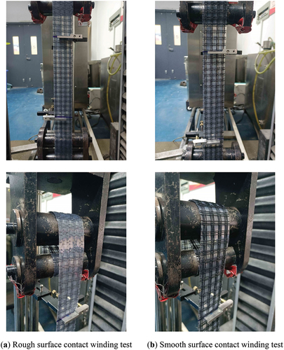
Table 1. The tensile strength of STFE membrane with different test methods (N/5 cm).
Figure 12. The failure mode of the clamping test specimen.
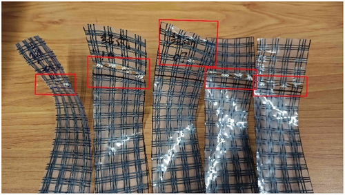
Figure 13. The numerical model of the dumbbell-shaped test.
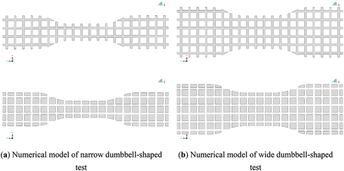
Table 2. The mechanical parameters of the fiber material.
Figure 14. The numerical result of the dumbbell-shaped test.
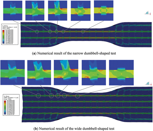
Figure 15. The stress concentration effect in dumbbell-shaped numerical simulation.
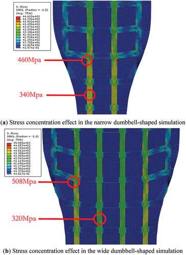
Figure 16. The failure mode of the dumbbell-shaped specimen.
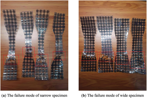
Figure 17. The comparison of rough and smooth surface contact winding test.
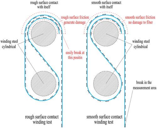
Table 3. The fracture elongation of STFE membrane with different test methods.
Figure 18. The stress-strain curve of clamping test and winding test.
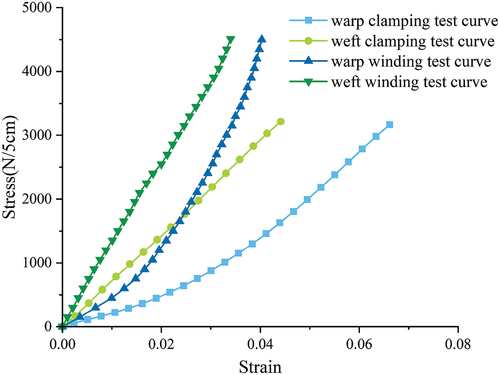
Table 4. The results of different membrane materials in tensile test.