
Figures & data
Table 1. Cross-sectional shapes of the 10 test specimens evaluated in this study.
Figure 1. Specifications of the bogie vibration measurement device proposed by the floor Construction Working Group of the Architectural Institute of Japan, YukaKoji WG (Citation2020a, Citation2020b).
Figure 2. Experimental setup.
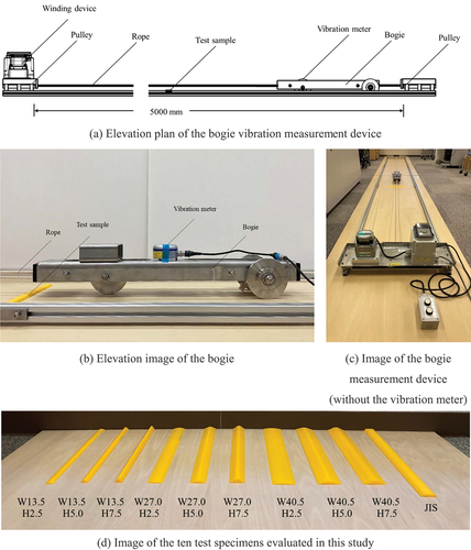
Figure 3. An example vibration level (LV) measurement (27.0 mm wide by 5.0 mm high curved specimen shown).
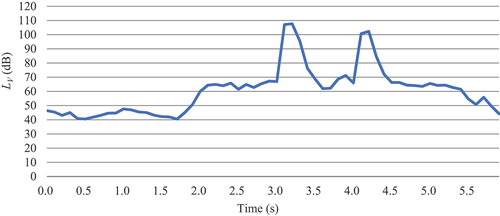
Figure 4. Comparison of the average maximum vibration level (LVavg.max) values.
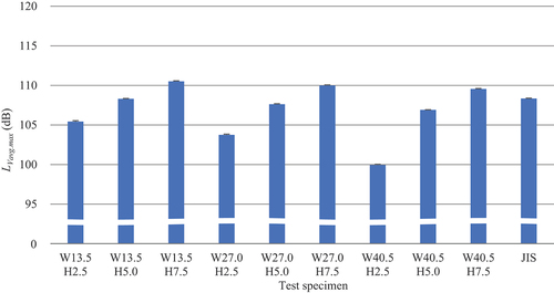
Figure 5. Relationship between the width of the curved protrusion and average maximum vibration level (LVavg.max).
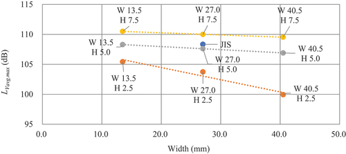
Figure 6. Relationship between the height of the curved protrusion and average maximum vibration level (LVavg.max).
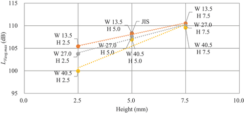
Figure 7. Relationship between the bogie passing speed and average maximum vibration level (LVavg.max).
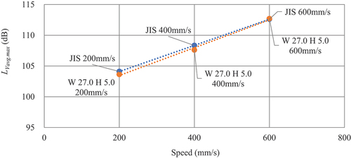
Table 2. Multiple comparisons of LVavg.max (using the JIS specimen at a passing speed of 400 mm/s as the Group 1 basis).
Table 3. Multiple comparisons of LVavg.max at different speeds for the JIS specimen and the 27.0 mm wide by 5.0 mm high curved specimen (using the JIS specimen at a passing speed of 400 mm/s as the Group 1 basis).
Table 4. Multiple comparisons of LVavg.max (using the 27.0 mm wide by 5.0 mm high curved specimen at a passing speed of 400 mm/s as the Group 1 basis).
Table 5. Multiple comparisons of LVavg.max at different speeds for the JIS specimen and the 27.0 mm wide by 5.0 mm high curved specimen (using the 27.0 mm wide by 5.0 mm high curved specimen at a passing speed of 400 mm/s as the basis).