Figures & data
Figure 1. Overturning and sliding of the cabinet due to inertial forces.
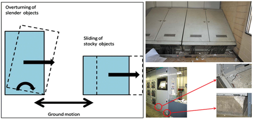
Figure 2. (a) seismic performance criteria for cabinets by field, (b) view of actual site installation, and (c) lower welded appearance in seismic performance evaluation.
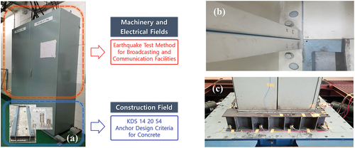
Figure 3. Setup for performance evaluation of static loading: (a) shear and (b) pull-out.
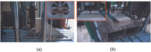
Figure 4. Static performance test failure mode: (a) shear and (b) pull-out.
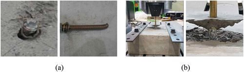
Figure 5. Typical load-displacement curves and maximum loads for each test: (a) shear and (b) pull-out.
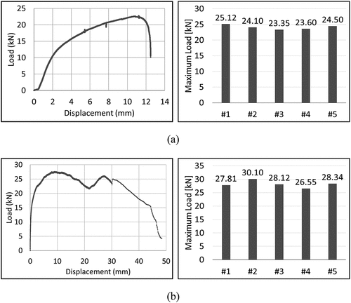
Figure 6. Specifications and composition of alternative test specimen.
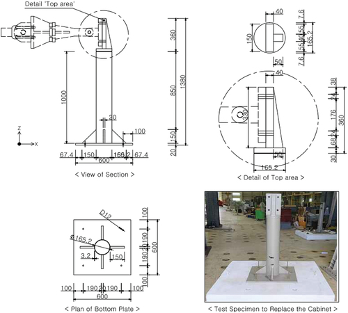
Figure 7. Design drawings of cracked concrete specimens.
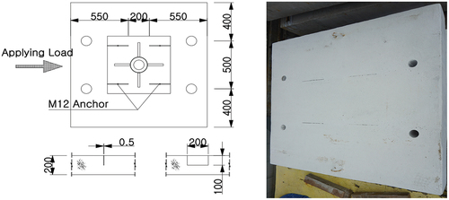
Figure 8. Overall installation view of the test specimen.
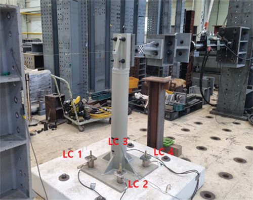
Figure 9. Failure type after the static loading test end.
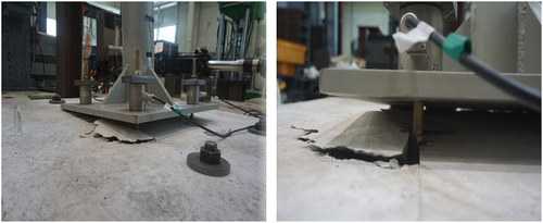
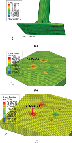
Figure 10. Simulated static loading test results and typical load-displacement curves.
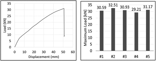
Figure 11. The tendency of tension and compressive load of post-installed anchor reflecting on-site installation conditions.
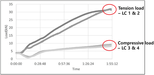
Figure 12. Various perspectives of specimen FE model.
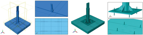
Figure 13. Numerical simulation boundary conditions for interfaces of different materials.
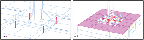
Figure 14. Stress-strain curve material properties for the anchor.
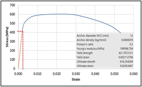
Figure 15. Response of concrete to a uniaxial loading condition: (a) compression behavior and (b) tension behavior.
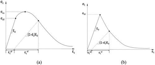
Table 1. Steel and concrete properties in the elastic region.
Table 2. Boundary condition parameter study to gain the anchor load.
Figure 16. Friction coefficient of the contact for each material: (a) steel to steel and (b) steel to concrete.
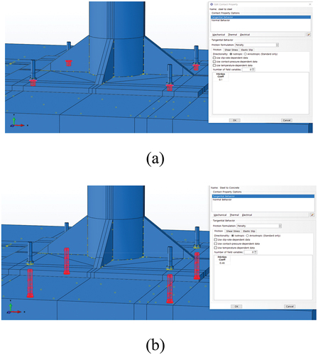
Figure 17. Deformation of an anchor embedded in concrete with displacement load.
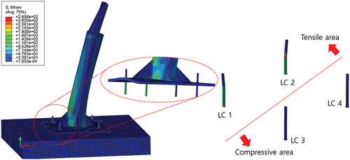
Figure 18. The results of the compression and tensile loads of the post-installed anchors in each case: (a) case 1, (b) case 2 and (c) case 3.
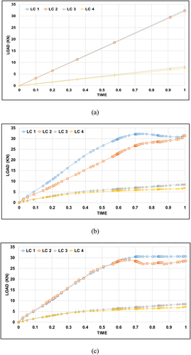
Figure 19. Comparison of maximum pull-out load of anchors according to boundary conditions: (a) case 1, (b) case 2 and (c) case 3.