Figures & data
Figure 1. Main components (a), a unit(b), a combination of units(c) in the deployable membrane system.
Figure 2. Joint between fabric and frame(a), frames with an I-shaped section(b), frames with a triangular section(c), frames with a rectangular section(d).
Figure 3. The generation process.
Figure 4. Rationalization of fabric surfaces and frame axes.
Figure 5. Geometry categories at the unit level.
Figure 6. Geometry categories at the combination level.
Figure 7. The folding diagram.
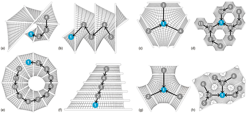
Figure 8. Geometry control through custom fabric contour.
Figure 9. Diagram of the three-roll bending machine.
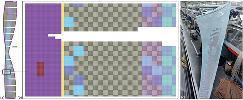
Figure 10. The knitted object(a), the pixel-based knitting pattern(b), enlarged detail of the knitting pattern(c).
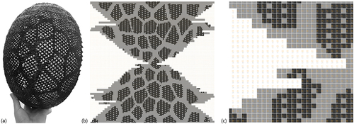
Figure 11. Diagram of the knitting pattern generation method.
Figure 12. A typical knitting pattern(a), a typical knitting diagram(b), a typical knit structure(c) of short row knitting.
Figure 13. The prototype.
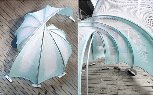
Figure 14. Parameters of the frame.
Figure 15. The FEA models during deployment(a)(b) and after deployment(c)(d).
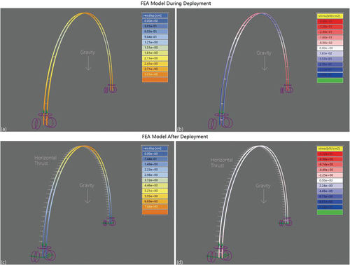
Figure 16. The effect of rise-span ratio(a)(b) and slenderness on max displacement(c)(d).
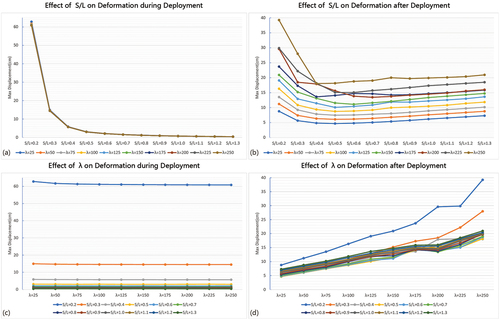
Figure 17. Parameters in the critical state of the overturning process.
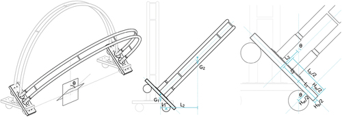
Figure 18. The folding process(a)-(f) and geometric comparison(g) of the prototype.
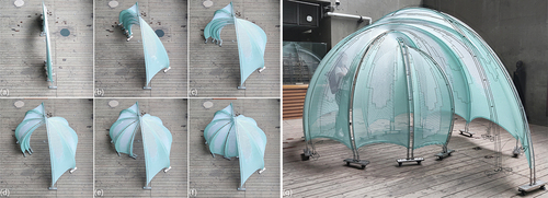
Figure 19. The knitting pattern(a)(b) and a piece of CNC-knitted fabric(c).