Figures & data
Figure 1. Solid and void analysis of typical plans with the original plan on the left (A, B, C, D) and the analysis on the right (A’, B’, C’, D’) that shows the three basic elements of which the typical plan consists of Source: Koolhaas Citation1998b, 336, 337, 338, 341 (A, B, C, D, respectively); graphics by author on the basis of the previously mentioned plans (A’, B’, C’, D’).
Figure 2. Allegory of the hypothetical connection between city and floor plan: Le Corbusier’s Saint-Dié (left) and the typical plan (right). Source: Rowe and Koetter Citation1978, 62 (left); graphic by author on the basis of Koolhaas Citation1998b, 336 (right).
Figure 3. SotV I (left) and SotV II (right) patents that are published in Content. Source: Koolhaas, McGetrick and OMA-AMO, Citation2004, 74 & 77, respectively.
Figure 4. Solid and void analysis of the Parc de la Villette: (A) original plan of the park; (B) voids: bands without programmatic elements (solids); (C) single void: isolated band; (D) solids and void: programmatic elements (solids) on a band (void). Source: Koolhaas Citation1998b, 923 (A); graphic by author on the basis of A (B – D).
Figure 5. Convention center from outside. Source: Koolhaas Citation1998a, p. 103.
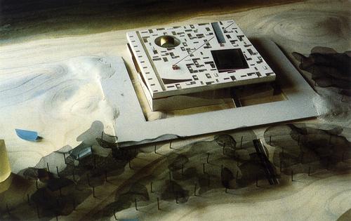
Figure 6. Bottom half of the building: visible the covered plaza with its distinctive dunes. Source: Koolhaas Citation1998a, p. 115.
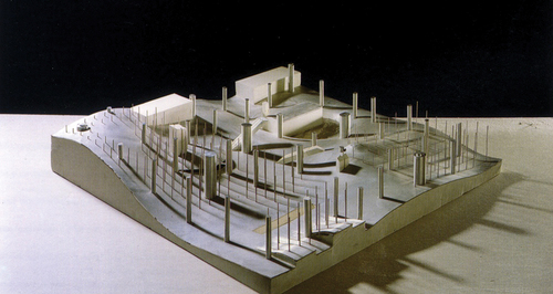
Figure 7. Section plans of the convention center. Clearly visible are its two distinctive features: the void (covered plaza), which lies in between two solids (building mass), and the solid’s wavy surface, called dunes. Source: Koolhaas Citation1998b, p. 383.
Figure 8. Void design strategy 1: (A) solid block; (B) solid block with cutting line; (C) cut block with both halves separated to create a void in between; (D) final composition of solid and void. Source: graphic by author.
Figure 9. Void design strategy 2: (A) solid block; (B) solid block with cutting lines; (C) removal of the solid matter between the cutting lines to create an initial void; (D) separation of both halves to expand the void; (E) final composition of solid and void. Source: graphic by author.
Figure 10. Void design strategy 3: (A) solid block; (B) solid block with cutting line; (C) cut block with both halves separated to create an initial void in between; (D) solid halves with excavation/cutting line and void in between; (E) excavation/cutting matter from the solid to expand the void; (F) final composition of solid and void. Source: graphic by author.
Figure 11. Void design strategy 4: (A) solid block; (B) solid block with excavation lines; (C) excavation of matter from the solid block to create a void; (D) continuous excavation to create two solid halves with a void in between; (E) separation of both halves to expand the void; (F) final composition of solid and void. Source: graphic by author.
Figure 12. Koolhaas’ usage of Albert’s parvis as a conceptual idea for the building. Source: Koolhaas Citation1996, 126–127.
Figure 13. Model photo of the library (left) and diagram of the interior boulevard (right) that runs through the entire building. Source: Koolhaas Citation1996, 141 (left); Koolhaas Citation1998b, 1312 (right).
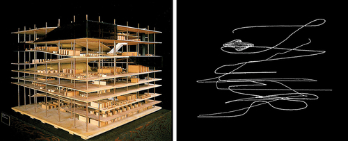
Figure 14. Second, third, and fourth floor (from left to right). Clearly visible, the internal boulevard (path) indicated with arrows, which is surrounded by the library elements (program). Source: Koolhaas Citation1996, p. 137.
Figure 15. Analysis of the rotated-section: (A) original assembled section; (B) extraction of the boulevard; (C) isolated boulevard; (D) solid and void diagram of the section. Source: Koolhaas Citation1996, 140–141 (A); graphics by author on the basis of a (B – D).
Figure 16. Solid and void plan of the campus center with “void-lines” (paths) that run through a solid mass (building), evoking to cut it apart. Source: Koolhaas Citation2006, 339 (edited by author).
Figure 17. Programmatic clusters: five stability clusters (left) and the four instability clusters between them (right).Source: Koolhaas Citation2007, p. 72.
Figure 18. Model of the Seattle Central Library with the visible platforms, the so-called stability clusters, and the spaces between them, the so-called instability clusters.Source: Koolhaas Citation2007, p. 72.
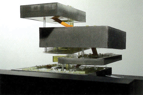
Figure 19. Solid and void elements at the ZKM: structural concept from Koolhaas’ writing “last apples” (left) and an analysis of the building’s section plan with indicated solid (black) and void (white) elements (right). Source: Koolhaas Citation1998b, 675 (left); Koolhaas Citation1998c, 89 (right; edited by author).
Figure 20. Genealogy of the strategy of the void, which is structured in three different tiers. Source: graphic by author.
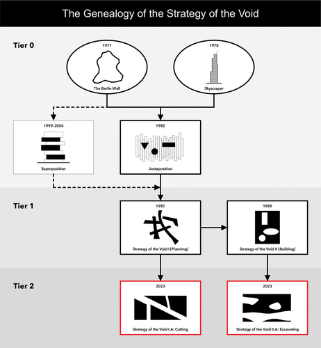
Figure 21. From the Berlin Wall and the skyscraper to the void design method of juxtaposition, which juxtaposes voids to create a completely new whole (concept). Source: graphic by author.
Figure 22. Void creation method 1: subdivision. Source: graphic by author.
Figure 23. Void creation method 2: deduction. Source: graphic by author.
Figure 24. Minimum amount of voids to perform the design method. Source: graphic by author.
Figure 25. The design method’s field of application is two-dimensional and lies on the XZ axis. Source: graphic by author.
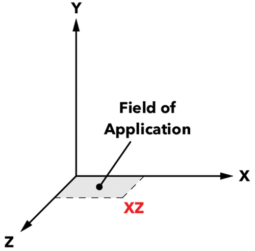
Figure 26. The design method’s field of application in plan is bound to the floor plan. Source: graphic by author.
Figure 27. From the Berlin Wall and the skyscraper to the void design method of superposition, which alternately superposes voids and solids to create a contrast. Source: graphic by author.
Figure 28. Types of contrasts (examples): different load bearing structure, room height, and lighting (from left to right). Source: graphic by author.
Figure 29. Type of superposition and shape of the voids and solids (based on Figure 28): the alternating superposition of voids and solids that can adopt various shapes based on their used contrast. Source: graphic by author.
Figure 30. The design method’s field of application is two- and three-dimensional and lies on the XY, YZ, or XYZ axis Source: graphic by author.
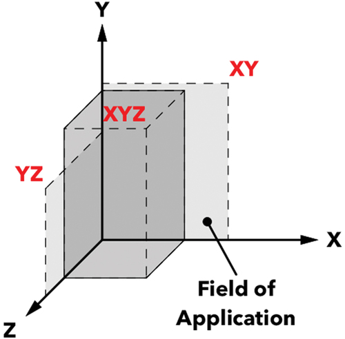
Figure 31. The design method’s field of application in plan is bound to the section, elevation, and 3D-model. Source: graphic by author.
Figure 32. The establishment of a network (circulation): the cut through a solid creates a void that functions as a connective element. Source: graphic by author.
Figure 33. Path type with example widths: linear path that can adopt different widths. Source: graphic by author.
Figure 34. Dimensions of the void: the cutting line’s width correlates with the width of the created void. Source: graphic by author.
Figure 35. The design method’s field of application is two-dimensional and lies on the XY, YZ, or XZ axis. Source: graphic by author.
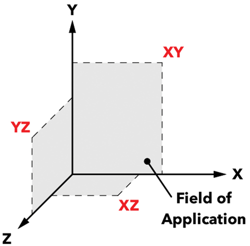
Figure 36. The design method’s field of application in plan is bound to the floor plan and section. Source: graphic by author.
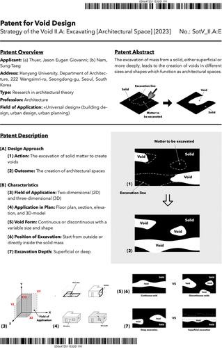
Figure 37. The creation of architectural spaces: the excavation of mass from a solid creates a void that functions as an architectural space. Source: graphic by author.
Figure 38. Type, shape, size, and the position of excavation of the voids: continuous vs. discontinuous voids of variable shapes and sizes whose excavation can either start from outside or inside a solid mass. Source: graphic by author.
Figure 39. Types of excavation depth: deep excavation vs. superficial excavation. Source: graphic by author.
Figure 40. The design method’s field of application is two- and three-dimensional and lies on the XY, YZ, XZ, or XYZ axis. Source: graphic by author.
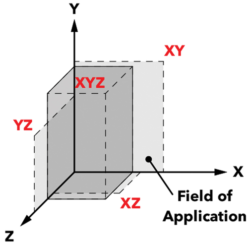
Figure 41. The design method’s field of application in plan is bound to the floor plan, section, elevation, and 3D-model. Source: graphic by author.