Figures & data
Figure 1. Comparison diagram of the three structures:(a) base isolated structure, (b) inter-storey isolated structure, (c) new staggered storey isolated structure (blank area represents frame, black shaded area represents isolated bearings).
Figure 2. Schematic diagram of the new staggered storey isolated structure.
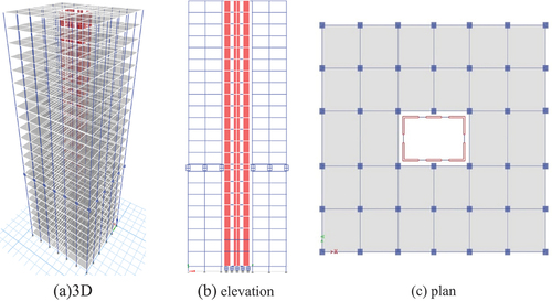
Table 1. Section size parameters.
Figure 3. Material stress-strain curve: (a) concrete; (b) steel.
Figure 4. Plastic hinge curve (IO immediate occupancy; LS life safety; CP collapse prevention).
Figure 5. Force-displacement relationship of LRB.
Table 2. Bearing parameters.
Table 3. Detailed information of the mainshock-aftershock ground motion sequences.
Figure 6. Acceleration time history of the mainshock-aftershock earthquake sequence.
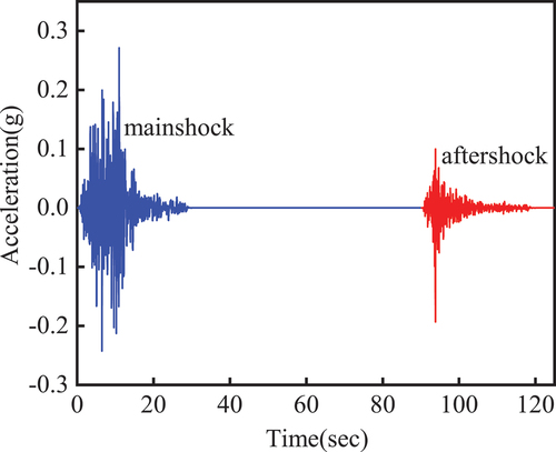
Figure 7. Response spectrum curve of mainshock-aftershock sequences.
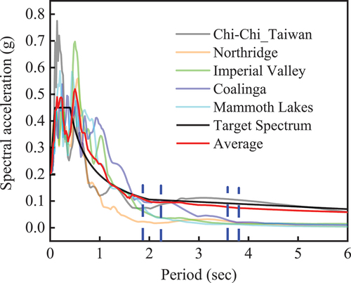
Table 4. Period comparison before and after isolated.
Figure 8. Inter-storey displacement of the new staggered storey isolated structure: (a) single mainshock; (b) mainshock-aftershock.
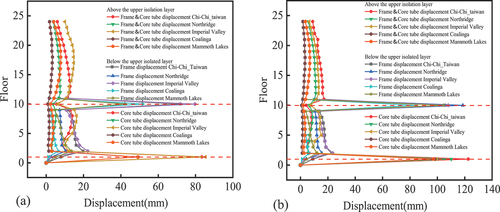
Figure 9. Inter-storey displacement of the fixed-base structure: (a) single mainshock; (b) mainshock-aftershock.

Figure 10. Displacement comparison of staggered isolated bearings under mainshock-aftershock sequences.
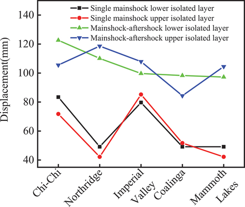
Figure 11. New staggered layer isolated structure with different isolated layers: (a)the 1rd floor (base isolated structure), (b) the 3rd floor, (c) the 6rd floor, (d) the 8rd floor.
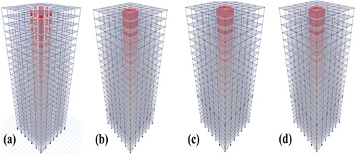
Figure 12. Base shear at different locations of upper isolated layer.
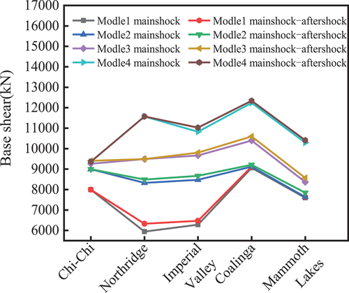
Figure 13. Base torque at different locations of upper isolated layer.
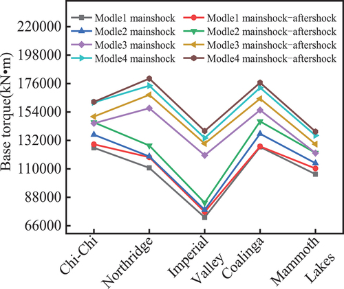
Figure 14. Inter-layer displacement angle at different locations of upper isolated layer.
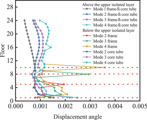
Table 5. Stress and deformation of isolated bearings.
Figure 15. Stress distribution in core tube influences force: single mainshocks (a) and (c); mainshock-aftershocks (b) and (d).
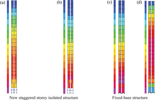
Figure 16. Distribution of frame plastic hinge: single mainshocks (a) and (c); mainshock-aftershocks (b) and (d).
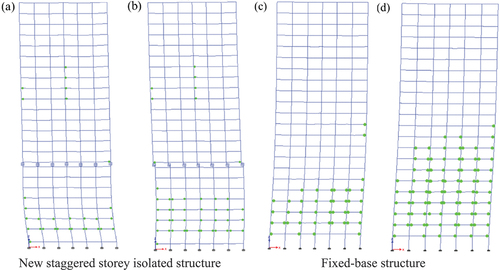
Figure 17. Hysteresis curve of isolated bearing under single mainshock and mainshock-aftershock sequences: (a) the upper isolated layer bearing; (b) the lower isolated layer bearing.
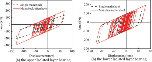
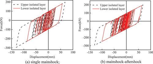
Figure 18. Hysteretic curves of upper and lower isolated layer bearings: (a) single mainshock; (b) mainshock-aftershock.