
Figures & data
Figure 1. Friction pendulum system.
Figure 2. Curved bridge considered for the study.
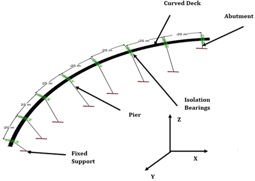
Figure 3. Analytical model of friction pendulum system (FPS), force deformation behaviour of FPS.
Table 1. Parameters of selected ground motions.
Figure 4. Response of bridge to unidirectional (a–c) and bidirectional (d–f) G.M.-1, G.M.-2, and G.M.-3 at different incident angles.
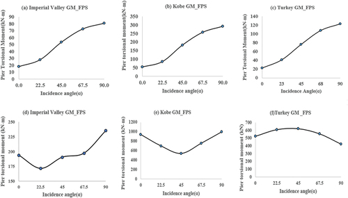
Figure 5. Response of bridge under unidirectional G.M.-1 (a-c), G.M.-2 (d-f) and G.M.-3 (g-i) due to different damping ratios of FPS.
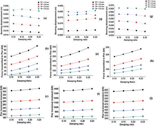
Figure 6. Response of bridge under unidirectional GM-1 (a–c), GM-2 (d–f) and GM-3 (g–i) due to different time periods of FPS.
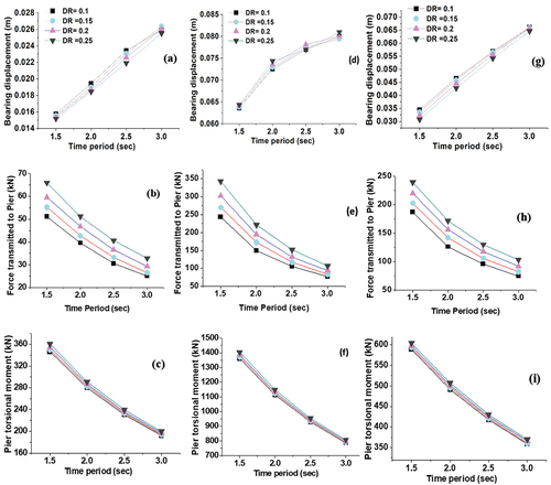
Figure 7. Response of bridge under bidirectional GM-1 (a–c), GM-2 (d–f) and GM-3 (g–i) due to different damping ratios of FPS.

Figure 8. Response of bridge under bidirectional G.M.-1 (a–c), G.M.-2 (d–f) and G.M.-3 (g–i) due to different time periods of FPS.
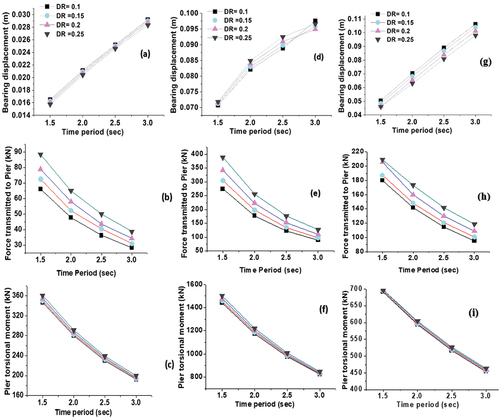
Figure 9. Peak results of the bridge for GM-1, GM-2, and GM-3.
Table 2. Different cases that were taken into consideration to compare the response of the bridge to a non-isolated condition.
Figure 10. The unidirectional and bidirectional ground motion response characteristics for the isolated curved bridge.
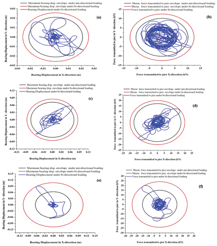
Figure 11. Response envelopes of the isolated bridge for GM-1 (a and b), GM-2 (c and d), and GM-3 (e and f).
Data availability statement
The data that support the findings of this study are available from the first named author, upon reasonable request. Any such requests should be made by emailing the first named author directly.