Figures & data
Figure 1. Robot-assisted magnetic capsule endoscope system architecture used in this study. (A) 3D model depicting the modular capsule architecture, (B) assembled capsule prototype, (C) external system consisting of the robot, EPM, external camera, external receiver and the test bench, (D) elliptical capsule shell, (E) cylindrical capsule shell.
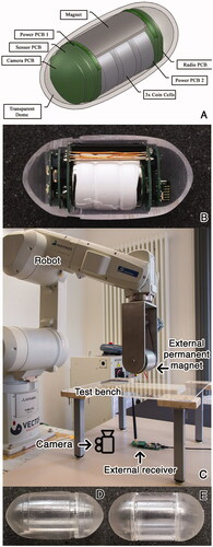
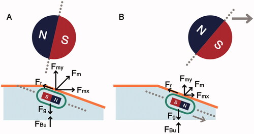
Figure 2. Capsule interaction with colon incline. (A) Capsule maintains contact with colon actuation surface, (B) capsule loses contact with the actuation surface due to increased capsule-manipulator distance.
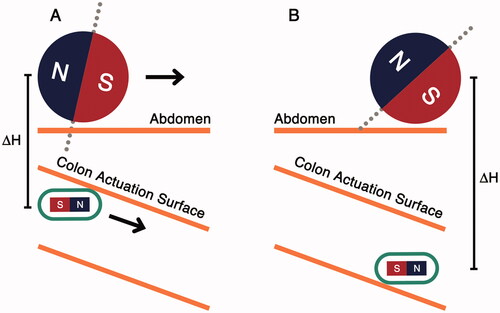
Figure 3. (A) Colon incline phantom with a straight and an inclined section at 20°, (B) phantom dimensions, (C) colon incline experimental setup using incline phantom lined with porcine colon.
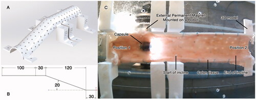
Figure 4. Colon incline navigation results. X-axis indicates the capsule tilt angle in degrees, left-handed Y-axis indicates the distance traversed by the capsule on the phantom in mm and right-handed Y-axis shows the ΔH trend. Navigation is improved by using elliptical capsule shell, tilting the capsule along the incline angle of the phantom, and by using water insufflation. (A) Results for cylindrical shell in air insufflated experiments. (B) Results for elliptical shell in air insufflated experiments. (C) Results for cylindrical shell in water insufflated experiments. (D) Results for elliptical shell in water insufflated experiments.
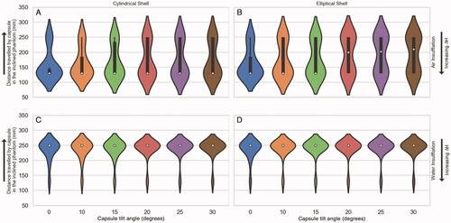
Figure 5. Capsule response to movement on the phantom. (A) Capsule encounters the start of incline, (B) manipulator moves forward, reducing the actuation force, (C) capsule drops and moves forward.
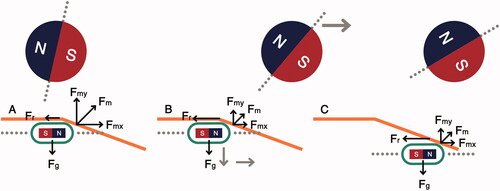
Figure 6. Capsule interaction with colon incline using water insufflation. (A) Capsule encounters the start of incline, (B) capsule follows the manipulator along the inclined surface due to lower friction and buoyant support from water.