
Figures & data
Figure 1. Classification schema for spatial data fusion processes.
Figure 2. Low-level subprocesses for spatial data fusion.
Figure 3. Interaction between SDI (OWS interface) and Semantic Web (RDF interface) components.
Figure 4. Proposed components for the formalization of feature relations.
Figure 5. Approaches to the management of feature relations between two data sources.
Figure 6. Usage patterns for spatial data fusion using Linked Data.
Figure 7. Implemented service infrastructure for spatial data fusion.
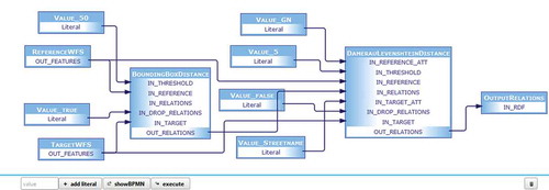
Figure 8. User-defined orchestration of WPS processes (screenshot).
Listing 1. Simplified RDF Turtle representation of a feature relation.
Figure 9. Sequence diagram for client-based compilation and execution of a data fusion process for defined spatial data sources.
Figure 10. Comparison of input datasets based on previously identified relationships (screenshot).
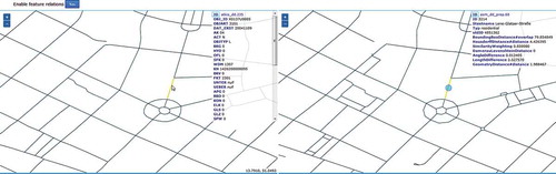
Figure 11. Identification schema for types of relations between road segments.
Table 1. Cardinality of relations with regard to the selected confidence threshold.
Listing 2. Pseudo-code of the workflow for the detection and creation of change sets between feature relations.
Listing 3. RDF-encoded relation between two OSM features expressed in terms of change sets.
Listing 4. Sample RDF relation between a polygon feature provided via WFS and an elevation raster provided via WCS.
Figure 12. Feature samples for the city of Dresden considered for the performance evaluation.
Table 2. Results of the performance evaluation.