Publication Cover
Mathematical and Computer Modelling of Dynamical Systems
Methods, Tools and Applications in Engineering and Related Sciences
Volume 13, 2007 - Issue 3
1,045
Views
3
CrossRef citations to date
0
Altmetric
Original Articles

Co-simulation and simulation integration for a full vehicle dynamic system

&
Pages 237-250 | Published online: 15 May 2007

Figures & data

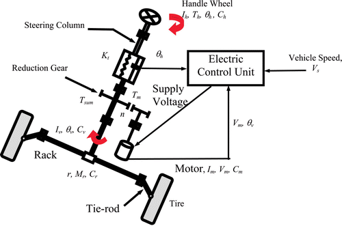
Figure 1. Diagram of the EPS mechanism.

Figure 1. Diagram of the EPS mechanism.

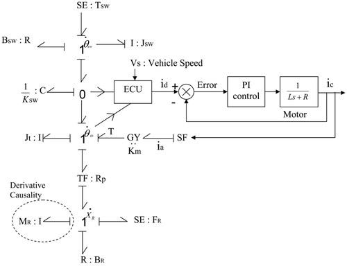
Figure 2. Bond graph model with derivative causality for a column-type EPS system.

Figure 2. Bond graph model with derivative causality for a column-type EPS system.

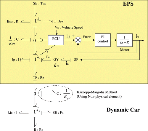
Figure 3. Bond graph model without derivative causality for a column-type EPS system.

Figure 3. Bond graph model without derivative causality for a column-type EPS system.

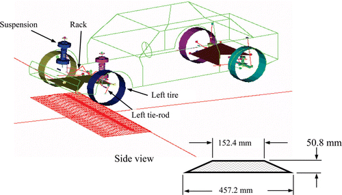
Figure 4. ADAMS full vehicle model and single-bump road profile.

Figure 4. ADAMS full vehicle model and single-bump road profile.

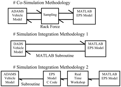
Figure 5. Different simulation techniques.

Figure 5. Different simulation techniques.

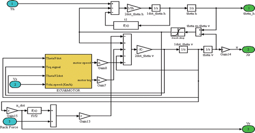
Figure 6. Control block diagram of EPS system.

Figure 6. Control block diagram of EPS system.

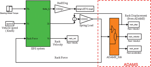
Figure 7. Concurrent simulation technique executing Matlab EPS and ADAMS mode.

Figure 7. Concurrent simulation technique executing Matlab EPS and ADAMS mode.

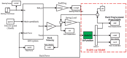
Figure 8. Simulation integration technique executing Matlab only with DADS subroutine.

Figure 8. Simulation integration technique executing Matlab only with DADS subroutine.

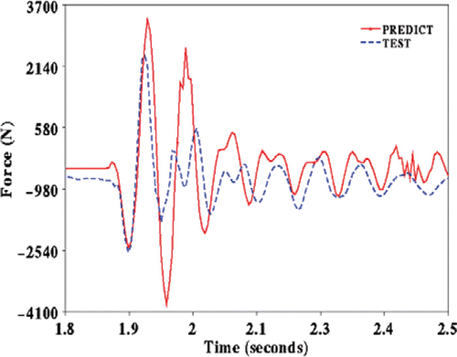
Figure 9. Load on the left front tie-rod.

Figure 9. Load on the left front tie-rod.

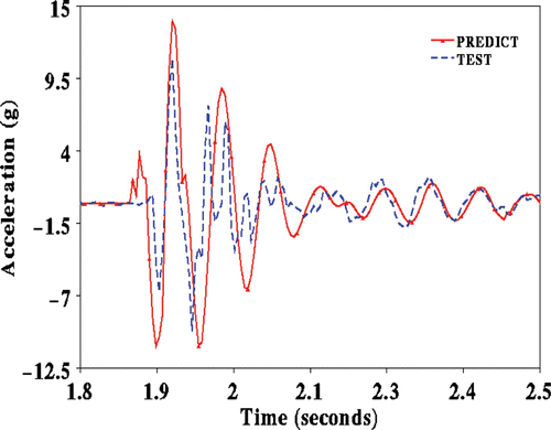
Figure 10. Left front tyre centre fore – aft acceleration.

Figure 10. Left front tyre centre fore – aft acceleration.

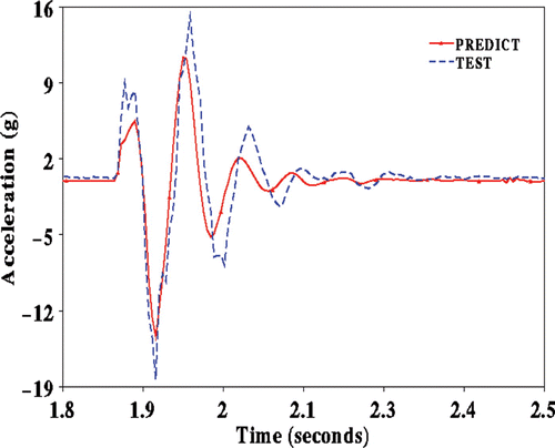
Figure 11. Left front tyre centre vertical acceleration.

Figure 11. Left front tyre centre vertical acceleration.

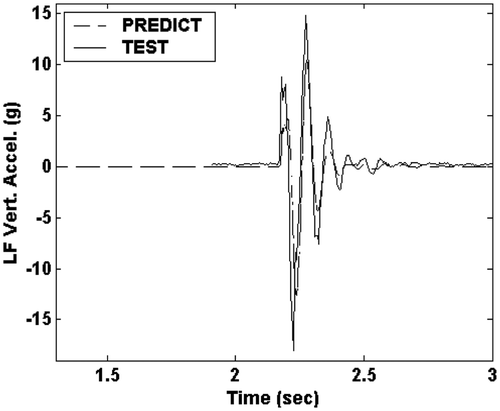
Figure 12. Comparison of the left front tyre centre vertical accelerations.

Figure 12. Comparison of the left front tyre centre vertical accelerations.

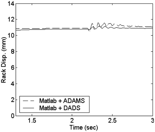
Figure 13. Comparison of rack displacements obtained using the co-simulation and simulation integration methods.

Figure 13. Comparison of rack displacements obtained using the co-simulation and simulation integration methods.

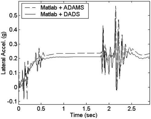
Figure 14. Comparison of lateral accelerations obtained using the co-simulation and simulation integration methods.

Figure 14. Comparison of lateral accelerations obtained using the co-simulation and simulation integration methods.

Reprints and Corporate Permissions

Please note: Selecting permissions does not provide access to the full text of the article, please see our help page How do I view content?

To request a reprint or corporate permissions for this article, please click on the relevant link below:

Academic Permissions

Please note: Selecting permissions does not provide access to the full text of the article, please see our help page How do I view content?

Obtain permissions instantly via Rightslink by clicking on the button below:

If you are unable to obtain permissions via Rightslink, please complete and submit this Permissions form. For more information, please visit our Permissions help page.