Publication Cover
Mathematical and Computer Modelling of Dynamical Systems
Methods, Tools and Applications in Engineering and Related Sciences
Volume 14, 2008 - Issue 5: Model Order Reduction
595
Views
23
CrossRef citations to date
0
Altmetric
Articles

Multi-parameter polynomial order reduction of linear finite element models

, , &
Pages 421-434 | Received 01 Feb 2007, Accepted 03 Jul 2007, Published online: 02 Oct 2008

Figures & data

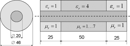
Figure 1. Coaxial probe. Geometry and material data. All dimensions are in millimetres.

Figure 1. Coaxial probe. Geometry and material data. All dimensions are in millimetres.

Figure 2. Coaxial probe. Magnitude of reflection coefficient as a function of frequency and relative permeability, as computed by the proposed algorithm.
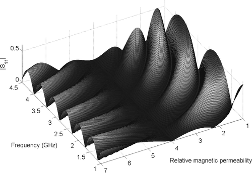
Figure 2. Coaxial probe. Magnitude of reflection coefficient as a function of frequency and relative permeability, as computed by the proposed algorithm.

Figure 3. Coaxial probe. Magnitude of error in reflection coefficient (37) as a function of frequency and relative permeability.
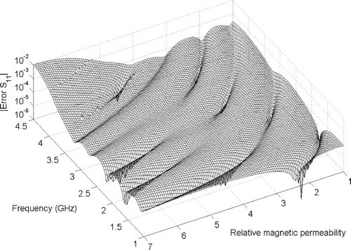
Figure 3. Coaxial probe. Magnitude of error in reflection coefficient (37) as a function of frequency and relative permeability.

Figure 4. Coaxial probe. Magnitude of error in reflection coefficient (37) as a function of frequency and relative permeability computed by direct implementation of definition (10) and post-orthogonalization.
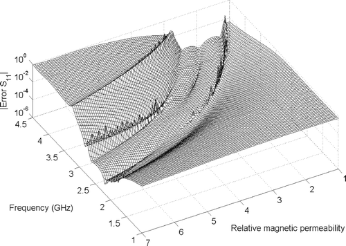
Figure 4. Coaxial probe. Magnitude of error in reflection coefficient (37) as a function of frequency and relative permeability computed by direct implementation of definition (10) and post-orthogonalization.

Figure 5. Patch antenna. Schematic of the geometry, featuring two different dielectrics. Dimensions are given in Citation21.
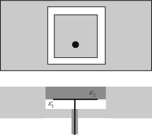
Figure 5. Patch antenna. Schematic of the geometry, featuring two different dielectrics. Dimensions are given in Citation21.

Figure 6. Patch antenna. Magnitude of reflection coefficient at ϵ r2 = 3 as a function of frequency and relative permittivity ϵ r1.
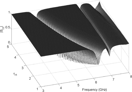
Figure 6. Patch antenna. Magnitude of reflection coefficient at ϵ r2 = 3 as a function of frequency and relative permittivity ϵ r1.

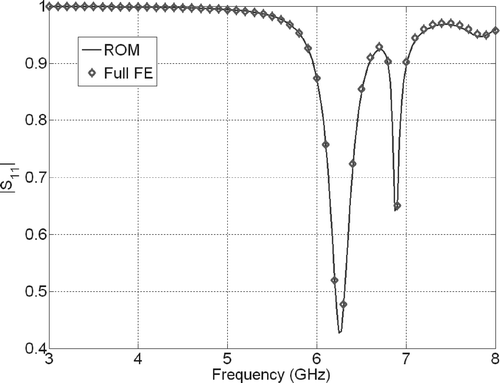
Figure 7. Patch antenna. Comparison of ROM with full FE simulations for ϵ r1 = 1 and ϵ r2 = 3.

Figure 7. Patch antenna. Comparison of ROM with full FE simulations for ϵ r1 = 1 and ϵ r2 = 3.

Figure 8. Patch antenna. Magnitude of error in reflection coefficient (37) as a function of frequency. Parameters ϵ r1 = 1, ϵ r2 = 3.
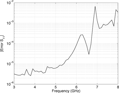
Figure 8. Patch antenna. Magnitude of error in reflection coefficient (37) as a function of frequency. Parameters ϵ r1 = 1, ϵ r2 = 3.
Reprints and Corporate Permissions

Please note: Selecting permissions does not provide access to the full text of the article, please see our help page How do I view content?

To request a reprint or corporate permissions for this article, please click on the relevant link below:

Academic Permissions

Please note: Selecting permissions does not provide access to the full text of the article, please see our help page How do I view content?

Obtain permissions instantly via Rightslink by clicking on the button below:

If you are unable to obtain permissions via Rightslink, please complete and submit this Permissions form. For more information, please visit our Permissions help page.