1,649
Views
3
CrossRef citations to date
0
Altmetric
Articles

Mathematical modelling of a domestic heating system with stratified storage tankFootnote

, &
Pages 231-248 | Received 30 Oct 2006, Accepted 17 Aug 2007, Published online: 08 Apr 2008

Figures & data

Figure 1. Heating unit with stratified storage tank, control unit, loading pump, burner, counter current heat exchanger, and temperature sensors (NTC 1 and NTC 2).
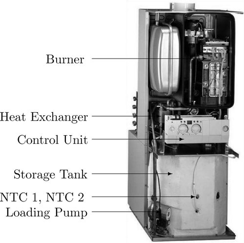
Figure 1. Heating unit with stratified storage tank, control unit, loading pump, burner, counter current heat exchanger, and temperature sensors (NTC 1 and NTC 2).

Figure 2. Sketch of the plant.

Figure 2. Sketch of the plant.

Figure 3. Graph of the finite state automaton describing the operational modes of the plant. For the sake of simplicity, transitions are labeled only unidirectionally, i.e. for each there exists a corresponding transition .
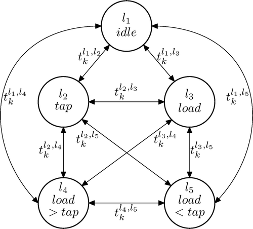
Figure 3. Graph of the finite state automaton describing the operational modes of the plant. For the sake of simplicity, transitions are labeled only unidirectionally, i.e. for each there exists a corresponding transition .

Figure 4. Sketch of the counter current heat exchanger with primary and secondary side temperature profiles Θpr(x,t) and Θsec(x,t) as well as the respective flow velocities v h(t) and v l(t).
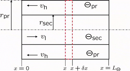
Figure 4. Sketch of the counter current heat exchanger with primary and secondary side temperature profiles Θpr(x,t) and Θsec(x,t) as well as the respective flow velocities v h(t) and v l(t).

Figure 5. Setup of the burner composed of the fan with the fan speed n F and the heat exchanging unit (pipe system) with the primary and secondary side temperatures τpr(ζ, t) and τsec(ζ, t) as well as the respective flow velocities v g(t) and v h(t).

Figure 5. Setup of the burner composed of the fan with the fan speed n F and the heat exchanging unit (pipe system) with the primary and secondary side temperatures τpr(ζ, t) and τsec(ζ, t) as well as the respective flow velocities v g(t) and v h(t).

Figure 6. Sketch of the heat exchanging part of the burner with the primary side, wall, and secondary side temperatures τpr, τw, and τsec as well as the respective flow velocities v g(t) and v h(t).
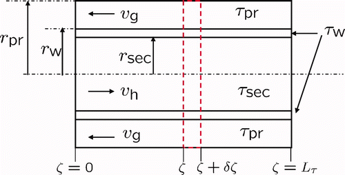
Figure 6. Sketch of the heat exchanging part of the burner with the primary side, wall, and secondary side temperatures τpr, τw, and τsec as well as the respective flow velocities v g(t) and v h(t).

Figure 7. Left: labeled scheme of the storage tank with respective in- and outflow velocities v l,d(t) and the resulting plug flow velocity v(t). Right: cross section of the storage wall with corresponding diameters d m , m = 1,2,3, heat conduction coefficients λ m , and heat transfer coefficients α n , n∈{i, a}.
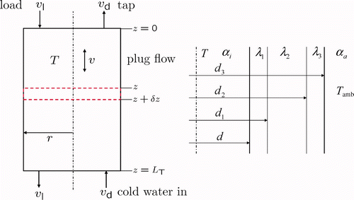
Figure 7. Left: labeled scheme of the storage tank with respective in- and outflow velocities v l,d(t) and the resulting plug flow velocity v(t). Right: cross section of the storage wall with corresponding diameters d m , m = 1,2,3, heat conduction coefficients λ m , and heat transfer coefficients α n , n∈{i, a}.

Figure 8. Finite volumes of discretized boundaries (ˆ) and PDE (•).

Figure 8. Finite volumes of discretized boundaries (ˆ) and PDE (•).

Figure 9. Structure for the classification of discretization schemes using exact system inversion of the distributed parameter system Σ.
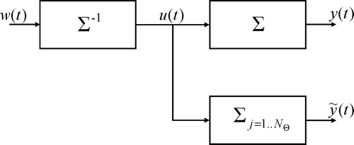
Figure 9. Structure for the classification of discretization schemes using exact system inversion of the distributed parameter system Σ.

Figure 10. Left: transient and stationary distortion due to spatial discretization of the heat exchanger PDE using N Θ = 50 compartments. Right: magnified version showing the transition between the transient and stationary region.
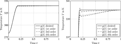
Figure 10. Left: transient and stationary distortion due to spatial discretization of the heat exchanger PDE using N Θ = 50 compartments. Right: magnified version showing the transition between the transient and stationary region.

Figure 11. Simulation results of the plant model for loading and tapping scenarios. Top left: tapping and loading velocities v d and v l. Bottom left: variation of the fan speed n F. Right: 3D temperature profile T(z,t) of the storage tank.
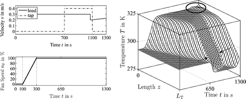
Figure 11. Simulation results of the plant model for loading and tapping scenarios. Top left: tapping and loading velocities v d and v l. Bottom left: variation of the fan speed n F. Right: 3D temperature profile T(z,t) of the storage tank.

Figure 12. Left: plot of the measured and simulated outlet temperatures of the primary and secondary side of the counter current heat exchanger. Right: measured and simulated temperature profiles at the secondary outlet of the condensing boiler.
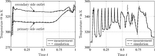
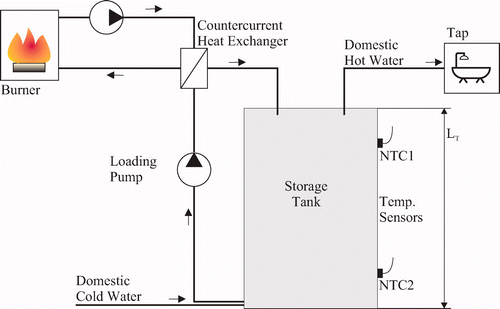
Figure 12. Left: plot of the measured and simulated outlet temperatures of the primary and secondary side of the counter current heat exchanger. Right: measured and simulated temperature profiles at the secondary outlet of the condensing boiler.
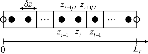
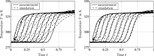
Figure 13. Measured and simulated temperature profiles for a loading scenario, using an upwind difference scheme for discretization of the PDE with N T  = 20 grid points (left) and N T  = 300 grid points (right).

Figure 13. Measured and simulated temperature profiles for a loading scenario, using an upwind difference scheme for discretization of the PDE with N T  = 20 grid points (left) and N T  = 300 grid points (right).

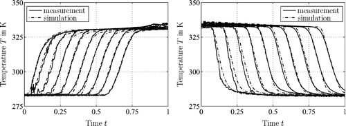
Figure 14. Plot of the measurements and simulations using the Superbee limiter and N T  = 21 grid points for the discretization of the PDE. Left: loading scenario l 3. Right: tapping scenario l 2.

Figure 14. Plot of the measurements and simulations using the Superbee limiter and N T  = 21 grid points for the discretization of the PDE. Left: loading scenario l 3. Right: tapping scenario l 2.

Reprints and Corporate Permissions

Please note: Selecting permissions does not provide access to the full text of the article, please see our help page How do I view content?

To request a reprint or corporate permissions for this article, please click on the relevant link below:

Academic Permissions

Please note: Selecting permissions does not provide access to the full text of the article, please see our help page How do I view content?

Obtain permissions instantly via Rightslink by clicking on the button below:

If you are unable to obtain permissions via Rightslink, please complete and submit this Permissions form. For more information, please visit our Permissions help page.