Figures & data
Figure 1. Part of a table of biomechanical data.
Figure 2. Time series of motion process data, stepwise mapped to neurons of a network, generating a neuron trajectory as a 2D representation of the motion.
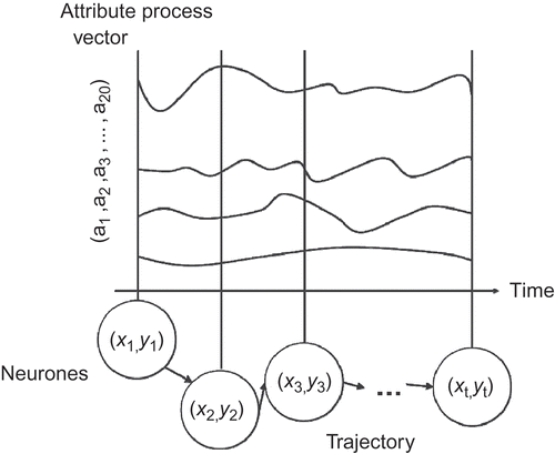
Figure 3. During training, patterns of data are mapped to the net, building clusters of similar types.
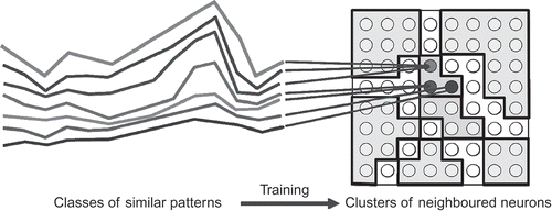
Figure 4. Time series of data, as are taken from motion processes, are mapped to the corresponding neurons of a trained network, generating trajectories in form of sequences of those activated neurons.
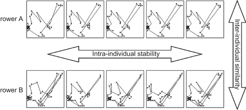
Figure 5. Different motions build different trajectories, and it has to be decided which ones are similar or not similar to each other. The trajectories ‘black’ and ‘dark grey’ in the centre seem to be similar, whereas ‘light grey’ and ‘black’ do not.
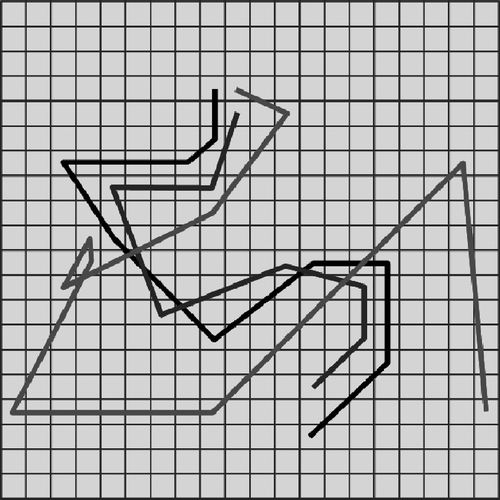
Figure 6. Using a semantic colouring for representing the types, the similarity of trajectories can be decided with respect to the sequences of types they represent. In the example the trajectories ‘light grey’ and ‘black’ are similar, whereas ‘dark grey’ and ‘black’ are not.
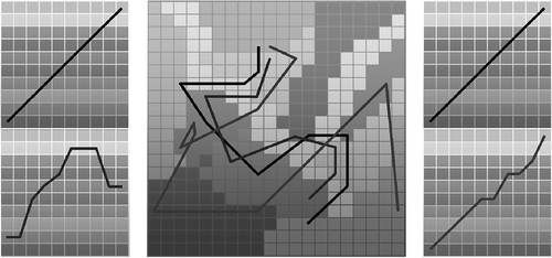
Figure 7. Faint trajectories from handball with highlighted examples in direct comparison.
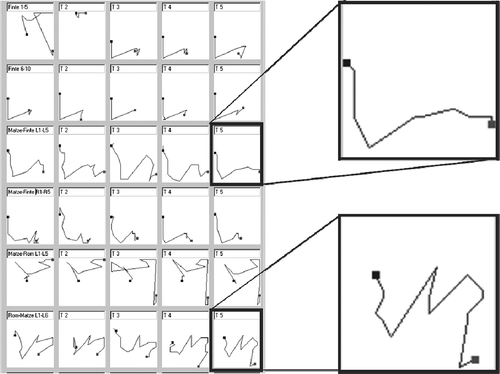
Figure 8. The lower faint trajectory from (left) transformed into a phase diagram (right) using phase colours (i.e. levels of grey).
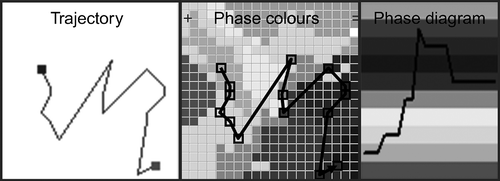
Figure 9. The table of faint trajectories from compared with the corresponding phase diagrams to find significant similarities and dissimilarities. Highlighted are the particular examples from .
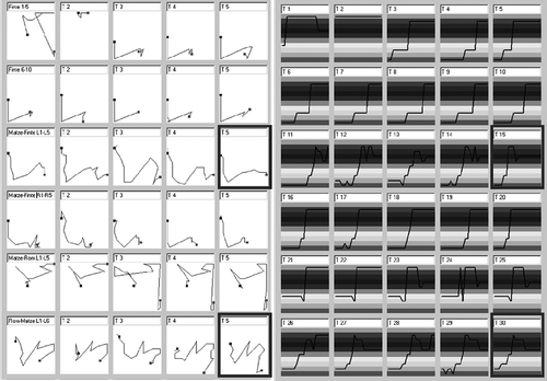
Figure 10. Replacing the phase colours by the corresponding ordinal numbers transforms the trajectories into attribute vectors that can be taken for a net training.
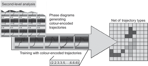
Figure 11. In the basic first step, the data net (left) generates a collection of trajectories (right).
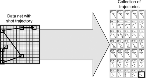
Figure 12. Basic net with phase colours (left) generating phase diagrams (centre), which generate a net of shot types (right).
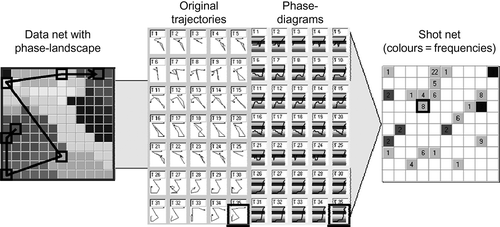
Figure 13. After colouring the net of shot types from with type colours (centre), the phase diagrams of the shots can be transferred to shot type diagrams (right), which can be taken for an easy comparison of the shot types.
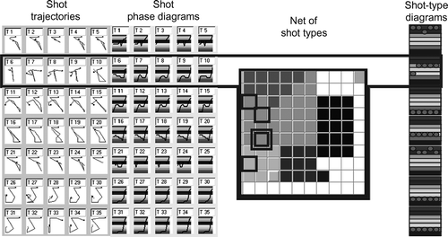
Figure 14. The complete analysing process, starting with the first-level analysis resulting in phase diagrams (left), continued with generating the second-level network for trajectory typing (centre) and completed by calibrating the shots regarding types and qualities.