Publication Cover
Mathematical and Computer Modelling of Dynamical Systems
Methods, Tools and Applications in Engineering and Related Sciences
Volume 18, 2012 - Issue 6
427
Views
0
CrossRef citations to date
0
Altmetric
Original Articles

Modelling of lateral dynamics for an endless metal process belt

&
Pages 571-586 | Received 27 Sep 2011, Accepted 20 Mar 2012, Published online: 23 Apr 2012

Figures & data

Figure 1. Sketch of a two-drum conveyor line: (a) basic dimensions, running direction, lateral positions ζ1 and ζ4, and disturbances M d and F d ; (b) manipulated variables: swivel angles β1 and β4, tilting angle α.
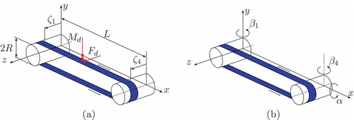
Figure 1. Sketch of a two-drum conveyor line: (a) basic dimensions, running direction, lateral positions ζ1 and ζ4, and disturbances M d and F d ; (b) manipulated variables: swivel angles β1 and β4, tilting angle α.

Figure 2. Situation of lateral belt position ζ for a swivel angle β and a thread slope θ in the horizontal xz plane. For the belt angle with respect to absolute coordinates κ = θ + β holds. The tangent to the belt's centre line at the point of first contact is denoted by T.
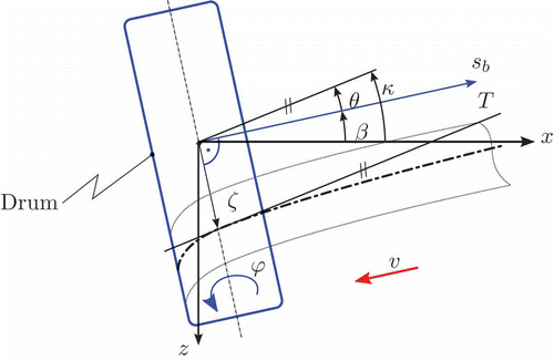
Figure 2. Situation of lateral belt position ζ for a swivel angle β and a thread slope θ in the horizontal x–z plane. For the belt angle with respect to absolute coordinates κ = θ + β holds. The tangent to the belt's centre line at the point of first contact is denoted by T.

Figure 3. Sketch of a two-drum conveyor line: (a) variables of the deformed belt: sketch of the conveyor belt modelled by an elastic beam; (b) indices of the belt system related to running direction.
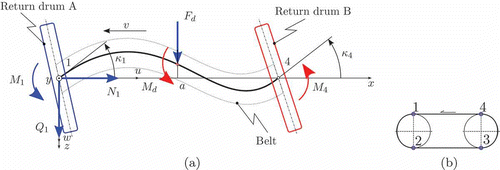
Figure 3. Sketch of a two-drum conveyor line: (a) variables of the deformed belt: sketch of the conveyor belt modelled by an elastic beam; (b) indices of the belt system related to running direction.

Figure 4. Sketch of the upper belt plane: the belt is split into subsections (a) I and (b) II. M 1, N 1, Q 1: moment, longitudinal and shear forces at point 1. M I , M II : inner bending moments in sections I and II.

Figure 4. Sketch of the upper belt plane: the belt is split into subsections (a) I and (b) II. M 1, N 1, Q 1: moment, longitudinal and shear forces at point 1. M I , M II : inner bending moments in sections I and II.

Figure 5. Transport delay and coupling between upper and lower belt as a consequence of hemicycle transportation on drum. Thread slope θ, drum radius R and lateral displacement Δζ are shown.
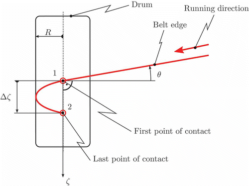
Figure 5. Transport delay and coupling between upper and lower belt as a consequence of hemicycle transportation on drum. Thread slope θ, drum radius R and lateral displacement Δζ are shown.

Figure 6. Geometric relations at tilted drum: tilt angle α1 causes a lateral displacement of Δζ1(α). Dashed line: drum position at operating point. Solid line: tilted drum. P 10: contact point in original position. P 1: contact point in tilted position. ζ10: original lateral displacement. ζ1: tilted lateral displacement.
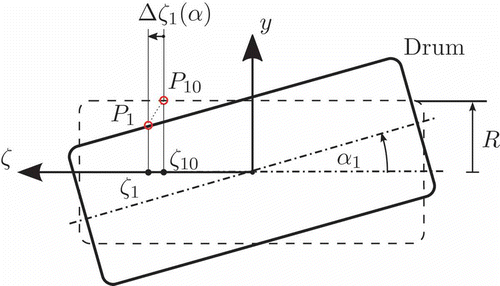
Figure 6. Geometric relations at tilted drum: tilt angle α1 causes a lateral displacement of Δζ1(α). Dashed line: drum position at operating point. Solid line: tilted drum. P 10: contact point in original position. P 1: contact point in tilted position. ζ10: original lateral displacement. ζ1: tilted lateral displacement.

Figure 7. Automated test rig for lateral dynamics of an endless metal belt.

Figure 7. Automated test rig for lateral dynamics of an endless metal belt.

Figure 8. Measured step responses for different swivel angle step inputs Δβ in °. Results for both positive and negative input amplitudes are shown. Sampling in spatial domain s b,s  = 0.1 m.
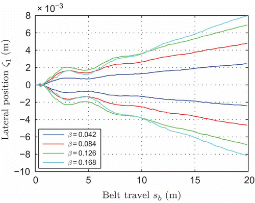
Figure 8. Measured step responses for different swivel angle step inputs Δβ in °. Results for both positive and negative input amplitudes are shown. Sampling in spatial domain s b,s  = 0.1 m.

Table 1. Stationary values for step responses with increasing step size

Table 2. Identification results of s b,adj for different step sizes

Figure 9. Validation in spatial domain: step response to swivel angle Δβ1 = 0.042: measurement: measured signal of ζ1, first order: beam with N 1 = 0, second order: beam with N 1 ≠ 0, first order GB: grey-box model utilizing s adj.
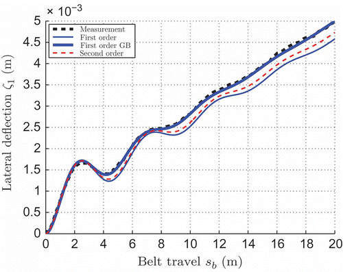
Figure 9. Validation in spatial domain: step response to swivel angle Δβ1 = 0.042: measurement: measured signal of ζ1, first order: beam with N 1 = 0, second order: beam with N 1 ≠ 0, first order GB: grey-box model utilizing s adj.
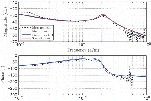
Figure 10. Validation in frequency domain: measurement: measured signal and spectral estimation of ζ1, first order: beam with N 1 = 0, second order: beam with N 1 ≠ 0, first order GB: grey-box model utilizing s adj.

Figure 10. Validation in frequency domain: measurement: measured signal and spectral estimation of ζ1, first order: beam with N 1 = 0, second order: beam with N 1 ≠ 0, first order GB: grey-box model utilizing s adj.

Figure 11. Relative phase error e of the Padé-approximation with respect to normalized period P of lateral belt dynamics.
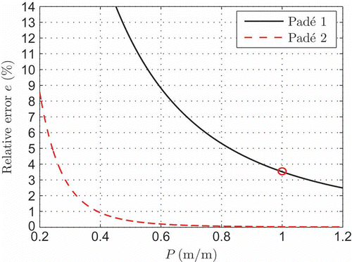
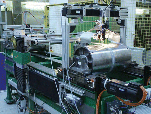
Figure 11. Relative phase error e of the Padé-approximation with respect to normalized period P of lateral belt dynamics.
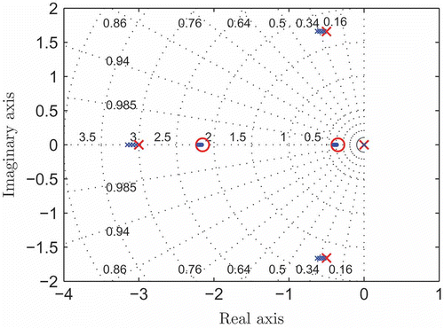
Figure 12. Pole zero plot of analytical model parameterized by force N 1. A cross denotes a pole (large red crosses designate the poles for N 1 = 0) and a circle marks a zero (large red circles designate zeros for N 1 = 0).

Figure 12. Pole zero plot of analytical model parameterized by force N 1. A cross denotes a pole (large red crosses designate the poles for N 1 = 0) and a circle marks a zero (large red circles designate zeros for N 1 = 0).

Figure 13. Lateral step disturbance F d at t = 5 s and closed-loop response.

Figure 13. Lateral step disturbance F d at t = 5 s and closed-loop response.

Reprints and Corporate Permissions

Please note: Selecting permissions does not provide access to the full text of the article, please see our help page How do I view content?

To request a reprint or corporate permissions for this article, please click on the relevant link below:

Academic Permissions

Please note: Selecting permissions does not provide access to the full text of the article, please see our help page How do I view content?

Obtain permissions instantly via Rightslink by clicking on the button below:

If you are unable to obtain permissions via Rightslink, please complete and submit this Permissions form. For more information, please visit our Permissions help page.