Publication Cover
Mathematical and Computer Modelling of Dynamical Systems
Methods, Tools and Applications in Engineering and Related Sciences
Volume 19, 2013 - Issue 1
540
Views
5
CrossRef citations to date
0
Altmetric
Original Articles

The application of parameter sensitivity analysis methods to inverse simulation models

Pages 67-90 | Received 16 Mar 2012, Accepted 20 May 2012, Published online: 26 Jun 2012

Figures & data

Figure 1. Block diagram illustrating the relationship between the system model and the corresponding sensitivity model for the general case of a multi-input multi-output system model.
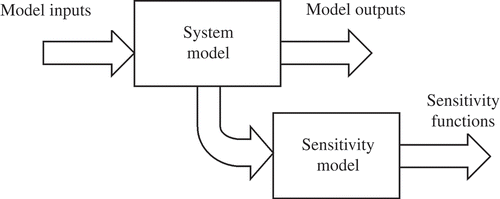
Figure 1. Block diagram illustrating the relationship between the system model and the corresponding sensitivity model for the general case of a multi-input multi-output system model.

Figure 2. Block diagram of inverse model and sensitivity model for the case of a linear time-invariant model described by a realizable inverse transfer function 1/G*(s).
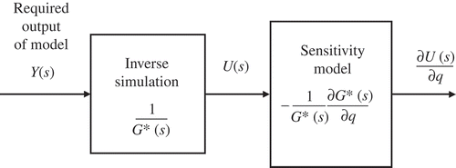
Figure 2. Block diagram of inverse model and sensitivity model for the case of a linear time-invariant model described by a realizable inverse transfer function 1/G*(s).

Figure 3. (a) Input signal required to give the specified repeated ramp output, as generated by inverse simulation. (b) Output of the model when subjected to input found from inverse simulation.
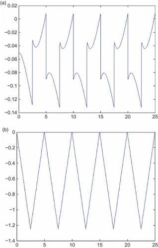
Figure 3. (a) Input signal required to give the specified repeated ramp output, as generated by inverse simulation. (b) Output of the model when subjected to input found from inverse simulation.

Figure 4. (a) Sensitivity function determined from the sensitivity model. (b) Sensitivity function determined using the parameter perturbation approach for a change of 10% in the parameter a.
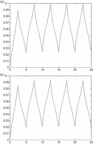
Figure 4. (a) Sensitivity function determined from the sensitivity model. (b) Sensitivity function determined using the parameter perturbation approach for a change of 10% in the parameter a.

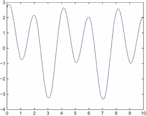
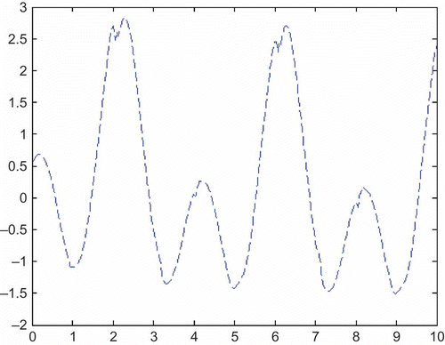
Figure 5. Sensitivity function determined from the sensitivity model.

Figure 5. Sensitivity function determined from the sensitivity model.

Figure 6. Sensitivity function determined from the sensitivity model.

Figure 6. Sensitivity function determined from the sensitivity model.

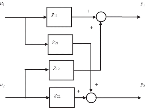
Figure 7. Block diagram of two-input two-output model considered in the example.

Figure 7. Block diagram of two-input two-output model considered in the example.

Figure 8. Block diagram of sensitivity model for determination of the inverse sensitivity for j parameters of a SISO linear model G(s) using the sensitivity model approach.
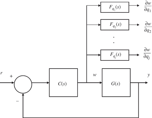
Figure 8. Block diagram of sensitivity model for determination of the inverse sensitivity for j parameters of a SISO linear model G(s) using the sensitivity model approach.

Figure 9. Root locus diagram, for the feedback system used for the inverse simulation of the transfer function G(s).
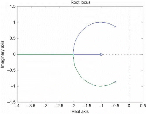
Figure 9. Root locus diagram, for the feedback system used for the inverse simulation of the transfer function G(s).

Figure 10. General form of block diagram for inverse simulation of a two-input two-output model. The signals w 1 and w 2 represent the inverse solutions.
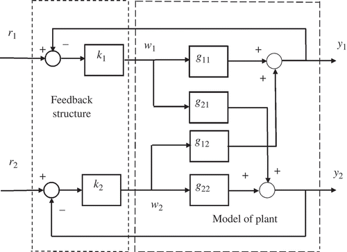
Figure 10. General form of block diagram for inverse simulation of a two-input two-output model. The signals w 1 and w 2 represent the inverse solutions.

Figure 11. Structure of Channel C1, which represents a single-input single-output model for the system-linking reference input r 1 and output y 1 with an additional disturbance pathway representing the effect of reference input r 2. For output y 1, this is equivalent to the structure of the two-input two-output diagram of Figure 10.
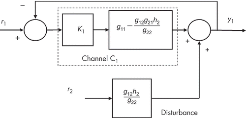
Figure 11. Structure of Channel C1, which represents a single-input single-output model for the system-linking reference input r 1 and output y 1 with an additional disturbance pathway representing the effect of reference input r 2. For output y 1, this is equivalent to the structure of the two-input two-output diagram of Figure 10.

Figure 12. Structure of Channel C2, which represents a single-input single-output model for the system linking reference input r 2 and output y 2 with an additional disturbance pathway representing the effect of reference input r 1. For output y 2, this is equivalent to the structure of the two-input two-output diagram of Figure 10.
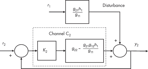
Figure 12. Structure of Channel C2, which represents a single-input single-output model for the system linking reference input r 2 and output y 2 with an additional disturbance pathway representing the effect of reference input r 1. For output y 2, this is equivalent to the structure of the two-input two-output diagram of Figure 10.

Figure 13. Inverse simulation results for the two-input two-output example for input w 1(t).

Figure 13. Inverse simulation results for the two-input two-output example for input w 1(t).

Figure 14. Inverse simulation results for the two-input two-output example for input w 2(t).

Figure 14. Inverse simulation results for the two-input two-output example for input w 2(t).

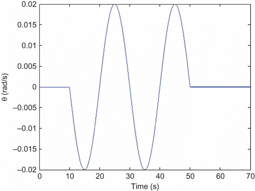
Figure 15. Stern-plane input signal found from inverse simulation for required trajectory involving a demanded sinusoidal change of pitch angle for gains of 300,000 in the feedback loop involving θ and 6000 in the feedback loop involving q.
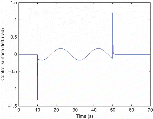
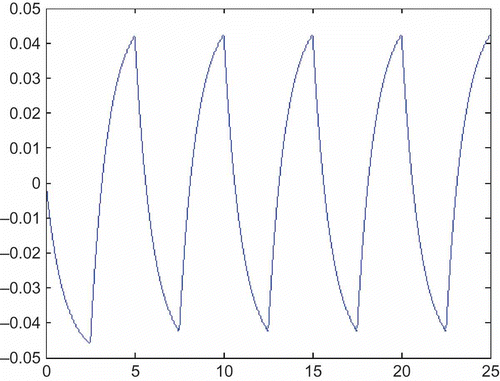
Figure 15. Stern-plane input signal found from inverse simulation for required trajectory involving a demanded sinusoidal change of pitch angle for gains of 300,000 in the feedback loop involving θ and 6000 in the feedback loop involving q.
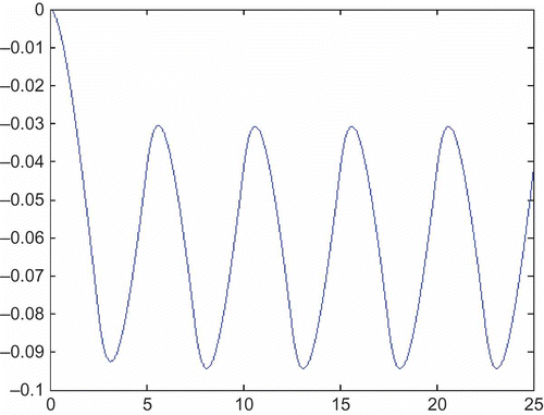
Figure 16. Pitch-angle record found from application of stern-plane deflection signal of Figure 15 to the forward model of the UUV in the absence of control surface limits.

Figure 16. Pitch-angle record found from application of stern-plane deflection signal of Figure 15 to the forward model of the UUV in the absence of control surface limits.

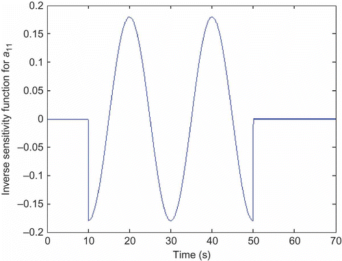
Figure 17. Sensitivity function found from sensitivity model for parameter a 11.

Figure 17. Sensitivity function found from sensitivity model for parameter a 11.

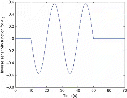
Figure 18. Sensitivity function found from sensitivity model for parameter a 12.

Figure 18. Sensitivity function found from sensitivity model for parameter a 12.

Reprints and Corporate Permissions

Please note: Selecting permissions does not provide access to the full text of the article, please see our help page How do I view content?

To request a reprint or corporate permissions for this article, please click on the relevant link below:

Academic Permissions

Please note: Selecting permissions does not provide access to the full text of the article, please see our help page How do I view content?

Obtain permissions instantly via Rightslink by clicking on the button below:

If you are unable to obtain permissions via Rightslink, please complete and submit this Permissions form. For more information, please visit our Permissions help page.